
Videos
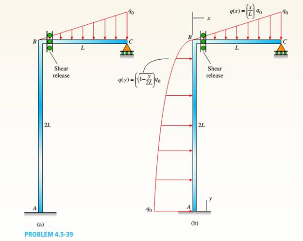
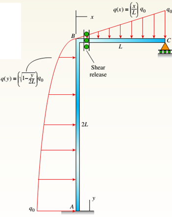
A plane frame (see figure) consists of column AB and beam BC that carries a triangular distributed load (see figure part a). Support A is fixed, and there is a roller support at C. Beam BC has a shear release just right of joint B.
- Find the support reactions at A and C then plot axial-force (N), shear-force (V), and bending-moment (M) diagrams for both members. Label all critical N,K and M values and also the distance to points where any critical ordinates are zero.
a.
The support reaction at point A and C and plot the shear, moment, and axial force diagram.
Answer to Problem 4.5.39P

Explanation of Solution
Given: .
The given figure.
AB column and BC beam forms the plane frame that carries a load that is distributed in the triangular shape. At C there is roller support and support A is fixed. Below the B joint there is a moment release at column AB
Concept Used:
Vertical force equilibrium is given as,
Horizontal force equilibrium is given as,
Calculation: .
Vertical force equilibrium is given as,
Horizontal force equilibrium is given as,
At the top of the moment release the moment is given as,
In equation (1),
Below B there is moment release at point A,
At x the shear force is given and equated to 0,
At point x bending moment is maximum,
Axial force critical values
Shear force critical values
Moment critical values
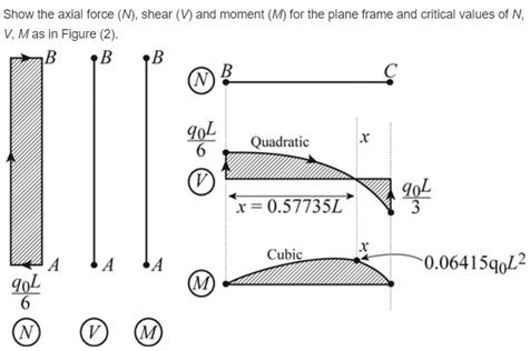
Conclusion: .
Thus, the support reaction at point A and C and plot the shear, moment and axial force diagram.
b.
For the load that is parabolic, lateral acts to the right added to AB column and part (a) is repeated.
Answer to Problem 4.5.39P
Explanation of Solution
Given: .
The given figure:.
AB column and BC beam forms the plane frame that carries a load that is distributed in the triangular shape. At C there is roller support and support A is fixed. Below the B joint, there is a moment release at column AB.
Concept Used:
Vertical force equilibrium is given as,
Horizontal force equilibrium is given as,
Calculation: .
With the equilibrium force being vertical,
Moment at point B above moment release,
In (2) substitute
With the equilibrium force being horizontal,
As left of x axis is negative,
At A moment below the moment release,
At x shear force is calculated and equated to 0,
At x bending moment is calculated
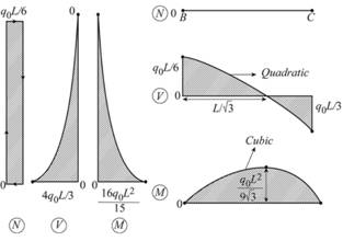
For plane frame and critical values of N, V, M, the axial, shear and moment is given.

Axial force critical values
Shear force critical values in beam
Shear force critical values in column
Moment critical values in beam
Moment critical values in column
Conclusion: .
Thus, for the load that is parabolic lateral acts to the right added to AB column and part (a) is repeated.
Want to see more full solutions like this?
Chapter 4 Solutions
Mechanics of Materials, SI Edition


- Beam ABCD represents a reinforced-concrete foundation beam that supports a uniform load of intensity q1= 3500 lb/ft (see figure). Assume that the soil pressure on the underside of the beam is uniformly distributed with intensity q2 Find the shear force VBand bending moment MBat point B. Find the shear force Vmand bending moment M at the midpoint of the beam.arrow_forwardFrame ABCD carries two concentrated loads (2P at T and P at ZX see figure) and also a linearly varying distributed load on AB, Find expressions for shear force Fand moment A/at x = L/3 of beam AB in terms of peak load intensity q0, force P, and beam length variable L. Let q0= P/L.arrow_forwardBeam ABC is fixed at support A and rests (at point B) upon the midpoint of beam DE (see part a of the figure). Thus, beam, ABC may be represented as a propped cantilever beam with an overhang BC and a linearly elastic support of stiffness k at point B (see part b of the figure). The distance from A to B is L = 10 ft, the distance from B to C is L/2 = 5 ft, and the length of beam DE is L = 10 ft. Both beams have the same flexural rigidity EI. A concentrated load P = 1700 lb acts at t lie free end of beam ABC. Determine the reactions RA, RB+ and MAfor beam ABC. Also, draw the shear-force and bending-moment diagrams for beam ABC, labeling all critical ordinates.arrow_forward
- A cantilever beam of W 12 × 14 section and length L = 9 ft supports a slightly inclined load P = 500 lb at the free end (see figure). Plot a graph of the stress o 4at point A as a function of the angle of inclination or Plot a graph of the angle L/3, which locates the neutral axis ma as a function of the angle a. (When plotting the graphs, let a vary from 0 to 10º) See Table F-1(a) of Appendix F for the dimensions and properties of the beam.arrow_forwardA beam ABCD with a vertical arm CE is supported as a simple beam al A and D (see figure part a). A cable passes over a small pulley that is attached to the arm at E. One end of the cable is attached to the beam at point B. (a) What is the force P in the cable if the bending moment in the beam just lo the left of point C is equal numerically to 640 lb-ft? Note: Disregard the widths of the beam and vertical arm and use centerline dimensions when making calculations. (b) Repeat part (a) if a roller support is added at C and a shear release is inserted just left of C (see figure part b).arrow_forwardA simple beam of span length 3.2 m carries a uniform load of intensity 48 kN/m, The cross section of the beam is a hollow box with wood flanges and steel side plates, as shown in the figure. The wood flanges are 75 mm x 100 mm in cross section, and the steel plates are 300 mm deep. What is the required thickness t of the steel plates if the allowable stresses are 120 M Pa for the steel and 6,5 M Pa for the wood? (Assume that the moduli of elasticity for the steel and wood are 210 GPa and 10 GPa, respectively, and disregard the weight of the beam.)arrow_forward
- A beam with a guided support and 10-ft span supports a distributed load of intensity q = 660 lb/ft over its first half (see figure part a) and a moment Mq = 300 ft-lb at joint B. The beam consists of a wood member (nominal dimensions 6 in. x 12 in. and actual dimensions 5.5 in. x 11.5 in. in cross section, as shown in the figure part b) that is reinforced by 0.25-in.-thick steel plates on top and bottom. The moduli of elasticity for the steel and wood are £s = 30 X 106 psi and £"w = 1.5 X 10⁶ psi, respectively. Calculate the maximum bending stresses trs in the steel plates and rw in the wood member due to the applied loads. If the allowable bending stress in the steel plates is = 14,000 psi and that in the wood is (T.dV!= 900 psi, find qmiiX. (Assume that the moment at .fi, A/0, remains at 300 ft-lb.) If q = 660 lb/ft and allowable stress values in part (b) apply, what is Müm^ at B?arrow_forwardSegments A B and BCD of beam A BCD are pin connected at x = 4 m. The beam is supported by a sliding support at A and roller supports at C and D (see figure). A triangularly distributed load with peak intensity of SO N/m acts on EC. A concentrated moment is applied at joint D. (a) Find reactions at supports A, C, and D. (b) Find internal stress resultants N, Y, and Mat x = 5m. (c) Repeat parts (a) and (b) for die case of the roller support at C replaced by a linear spring of stiffness kr™ 200 kN/m (see figure).arrow_forwardFind support reactions at A and D and then calculate the axial force N. shear force 1 and bending moment 11 at mid-span of column BD. Let L = 4 m, q0 = 160N/m, P = 200N, and M0= 380 N .m.arrow_forward
- Beam A BCD has a sliding support at A, roller supports at C and A and a pin connection at B (see figure). Assume that the beam has a rectangular cross section (b = 4 in., h = 12 in.). Uniform load q acts on ABC and a concentrated moment is applied at D. Let load variable q = 1750 lb/ft, and assume that dimension variable L = 4 ft. First, use statics to confirm the reaction moment at A and the reaction forces at Cand A as given in the figure. Then find the ratio of the magnitudes of the principal stresses (crj/os) just left of support Cat a distance d = 8 in. up from the bottom,arrow_forwardBeam A BCD has a sliding support at A, roller supports at C and A and a pin connection at B (see figure). Assume that the beam has a rectangular cross section (b = 4 in., h = 12 in.). Uniform load q acts on ABC and a concentrated moment is applied at D. Let load variable q = 1750 lb/ft, and assume that dimension variable L = 4 ft. First, use statics to confirm the reaction moment at A and the reaction forces at C and A as given in the figure. Then find the ratio of the magnitudes of the principal stresses (crj/os) just left of support Cat a distance d = 8 in. up from the bottom, The pedal and crank are in a horizontal plane and points A and B are located on the top of the crank. The load P = 160 lb acts in the vertical direction and the distances (in the horizontal plane) between the line of action of the load and points A and B are b\ = 5.0 in., h-, = 2.5 in., and/>3 = 1.0 in. Assume that the crank has a solid circular cross section with diameter d = 0.6 inarrow_forwardA wood beam with a rectangular cross section (see figure) is simply supported on a span of length L. The longitudinal axis of the beam is horizontal, and the cross section is tilted at an angle a. The load on the beam is a vertical uniform load of intensity q acting through the centroid C. Determine the orientation of the neutral axis and calculate the maximum tensile stress bmaxif PROBLEMS 6.4-2 and 6.4-3 b = 80 mm, b = 140 mm, L = 1,75 m, a — 22.5°, and q = 7.5 kN/m.arrow_forward
 Mechanics of Materials (MindTap Course List)Mechanical EngineeringISBN:9781337093347Author:Barry J. Goodno, James M. GerePublisher:Cengage Learning