
System Dynamics
3rd Edition
ISBN: 9780073398068
Author: III William J. Palm
Publisher: MCG
expand_more
expand_more
format_list_bulleted
Concept explainers
Videos
Textbook Question
Chapter 4, Problem 4.54P
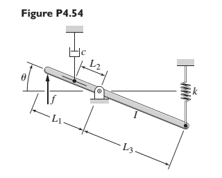
Derive the equation of motion for the lever system shown in Figure P4.54, with the force f as the input and the angle
Expert Solution & Answer
Want to see the full answer?
Check out a sample textbook solution
Students have asked these similar questions
For the mechanical system shown below, find the equation of motions and the system matrix. Where (x = X ewt)
Figure Q3(b) shows a uniform bar AB of mass = 8 kg hinged at point C. Point A is connected to a spring to maintain the bar in vertical direction, and the stiffness k = 500 N/m. If point A is displaced counter-clockwise by a small angle θ = 3.5 degree and released,
(i) With the free body diagram and kinetic diagram, determine the initial horizontal displacement of A.
MECHANICAL VIBRATIONS
The system shown in Fig. P3.3 consists of a uniform rod which has length 1, mass m, and mass moment of inertia about its mass center 1. The rod is supported by two springs which have stiffness coefficients ky and k2, as shown in the figure. Determine the system differential equation of motion for small oscillations. Determine also the system natural frequency.
Chapter 4 Solutions
System Dynamics
Ch. 4 - Prob. 4.1PCh. 4 - In the spring arrangement shown in Figure P4.2....Ch. 4 - In the arrangement shown in Figure P4.3, a cable...Ch. 4 - In the spring arrangement shown in Figure P4.4,...Ch. 4 - For the system shown in Figure P4.5, assume that...Ch. 4 - The two stepped solid cylinders in Figure P4.6...Ch. 4 - A table with four identical legs supports a...Ch. 4 - The beam shown in Figure P4.8 has been stiffened...Ch. 4 - Determine the equivalent spring constant of the...Ch. 4 - Compute the equivalent torsional spring constant...
Ch. 4 - Plot the spring force felt by the mass shown in...Ch. 4 - Calculate the expression for the natural frequency...Ch. 4 - Prob. 4.13PCh. 4 - Obtain the expression for the natural frequency of...Ch. 4 - 4.15 A connecting rod having a mass of 3.6 kg is...Ch. 4 - Calculate the expression for the natural frequency...Ch. 4 - For each of the systems shown in Figure P4.17, the...Ch. 4 - The mass m in Figure P4.18 is attached to a rigid...Ch. 4 - In the pulley system shown in Figure P4.19, the...Ch. 4 - Prob. 4.20PCh. 4 - Prob. 4.21PCh. 4 - Prob. 4.22PCh. 4 - In Figure P4.23, assume that the cylinder rolls...Ch. 4 - In Figure P4.24 when x1=x2=0 the springs are at...Ch. 4 - 4.25 In Figure P4.25 model the three shafts as...Ch. 4 - In Figure P4.26 when 1=2=0 the spring is at its...Ch. 4 - Prob. 4.27PCh. 4 - For the system shown in Figure P4.28, suppose that...Ch. 4 - For the system shown in Figure P4.29, suppose that...Ch. 4 - Prob. 4.30PCh. 4 - For Figure P4.31, the equilibrium position...Ch. 4 - Prob. 4.32PCh. 4 - Prob. 4.33PCh. 4 - 4.34 For Figure P4.34, assume that the cylinder...Ch. 4 - Use the Rayleigh method to obtain an expression...Ch. 4 - Prob. 4.36PCh. 4 - 4.37 Determine the natural frequency of the system...Ch. 4 - Determine the natural frequency of the system...Ch. 4 - Use Rayleigh's method to calculate the expression...Ch. 4 - Prob. 4.40PCh. 4 - Prob. 4.41PCh. 4 - Prob. 4.42PCh. 4 - The vibration of a motor mounted on the end of a...Ch. 4 - Prob. 4.44PCh. 4 - Prob. 4.45PCh. 4 - A certain cantilever beam vibrates at a frequency...Ch. 4 - Prob. 4.47PCh. 4 - 4.48 The static deflection of a cantilever beam is...Ch. 4 - Figure P4.49 shows a winch supported by a...Ch. 4 - Prob. 4.50PCh. 4 - Prob. 4.51PCh. 4 - Prob. 4.52PCh. 4 - 4.53 In Figure P4.53 a motor supplies a torque T...Ch. 4 - Derive the equation of motion for the lever system...Ch. 4 - Prob. 4.55PCh. 4 - Figure P4.56a shows a Houdaille damper, which is a...Ch. 4 - 4.57 Refer to Figure P4.57. Determine the...Ch. 4 - For the system shown in Figure P4.58, obtain the...Ch. 4 - Find the transfer function ZsXs for the system...Ch. 4 - Prob. 4.60PCh. 4 - Find the transfer function YsXs for the system...Ch. 4 - Prob. 4.62PCh. 4 - 4.63 In the system shown in Figure P4.63, the...Ch. 4 - Prob. 4.64PCh. 4 - Figure P4.65 shows a rack-and-pinion gear in which...Ch. 4 - Figure P4.66 shows a drive train with a spur-gear...Ch. 4 - Prob. 4.67PCh. 4 - Prob. 4.68PCh. 4 - Prob. 4.69PCh. 4 - Figure P4.70 shows a quarter-car model that...Ch. 4 - Prob. 4.71PCh. 4 - 4.72 Derive the equation of motion for the system...Ch. 4 - A boxcar moving at 1.3 m/s hits the shock absorber...Ch. 4 - For the systems shown in Figure P4.74, assume that...Ch. 4 - Refer to Figure P4.75a, which shows a ship’s...Ch. 4 - In this problem, we make all the same assumptions...Ch. 4 - Refer to Figure P4.79a, which shows a water tank...Ch. 4 - The “sky crane” shown on the text cover was a...Ch. 4 - Prob. 4.81PCh. 4 - Prob. 4.82PCh. 4 - Suppose a mass in moving with a speed 1 becomes...Ch. 4 - Consider the system shown in Figure 4.6.3. Suppose...Ch. 4 - Prob. 4.86PCh. 4 - Figure P4.87 shows a mass m with an attached...Ch. 4 - Figure P4.88 represents a drop forging process....Ch. 4 - Refer to Figure P4.89. A mass m drops from a...Ch. 4 - Prob. 4.90PCh. 4 - (a) Obtain the equations of motion of the system...Ch. 4 - Refer to part (a) of Problem 4.90. Use MATLAB to...Ch. 4 - Refer to Problem 4.91. Use MATLAB to obtain the...Ch. 4 - 4.94 (a) Obtain the equations of motion of the...Ch. 4 -
4.95 (a) Obtain the equations of motion of the...
Knowledge Booster


Learn more about
Need a deep-dive on the concept behind this application? Look no further. Learn more about this topic, mechanical-engineering and related others by exploring similar questions and additional content below.Similar questions
- A mass weighing 4 pounds is attached to a spring whose spring constant is 36 lb/ft. Find the equation of motion.arrow_forwardQuestion 4For the dynamic system shown in the figure,derive the equations of motion using Lagrange’s equations.arrow_forwardIn the mechanical system in the figure, a rigid rod is bedded at point P and has mass m at its end. can rotate vertically. At the other end of the rod, a spring (k) and a damper (c) are attached. Draw the Free-Body Diagram of the system, obtain the Equation of Motion (the vertical position of the ball We assume that the displacement x is very small and the bar is massless).arrow_forward
- PART OF MECHANICAL VIBRATIONS SUBJECT USE VIRTUAL WORK The uniform bar shown in Fig. P3.6 has mass m, length l, and mass moment of inertia 1 about its mass center. The bar is supported by two springs kı and k2, as shown in the figure. Obtain the differential equation of motion and determine the natural frequency of the system in the case of small oscillations.arrow_forwardFind the equations of motion of the system shown in the figure by using the coordinates ϴ1 and ϴ2. (Accept small angle for ϴ1 and ϴ2.)arrow_forwardIn the system shown in Figure 1, assume that the rod pivoted at point P is massless and perfectly rigid. A mass m is attached to the other end of the rod and supported by a damper at distance L, and a spring at a distance L2 to the pivot point P. The displacement x of the mass is measured from the equilibrium position of the system. Assuming that x is small, obtain the equation of motion of the system by applying Newton's laws.arrow_forward
- A uniform beam of length, L, and mass, M, is freely pivoted at one end about an attachment point in a wall. The other end is supported by a horizontal cable also attached to the wall, so that the beam makes an angle phi with the horizontal as shown below. To answer the questions below, find algebraic expressions for the tension in the cable, the angular acceleration of the beam, should the cable break, and the resulting angular velocity as the beam falls through the vertical position. A. If L = 2.4 m, M = 5 kg, and phi = 45o, then what is the tension in the cable? B. If the cable snaps, what is the angular acceleration about the pivot point? C. What is the angular velocity of the falling beam, just as it hits the wall?arrow_forwardFind the transfer function G(s) of the mechanical system below. Show complete solution and fbd.arrow_forwardIn the figure below Atwood’s machine is drawn - two masses and hanging over a massive pulley of rotational inertia and radius , connected by a massless unstretchable string. The string rolls on the pulley without slipping.a) Find the acceleration of the system and the tensions in the string on both sides of the pulley in terms of in terms of given variables.b) Why are the rope tensions on two sides of the pulley not the same? Explain it physically.c) Suppose mass and the system is released from rest with the masses at equal heights. When mass has descended a distance , find the velocity of each mass and the angular velocity of the pulley.[4***] A string is rolled around a cylinder( kg) as shown in figure. A person pulls on the string, causing the cylinder to roll without slipping along the floorarrow_forward
- Four masses m1, m2, m3 and m4 are 100 kg, 200 kg, 140 kg and 160 kg respectively. The corresponding radii of rotation are 0.2 m, 0.15 m, 0.25 m and 0.3 m respectively and the angles between successive masses are 30°, 75° and 100°. Find the position and magnitude of the balance mass required, graphically, if its radius of rotation is 0.2 m.arrow_forward'A model for the elbow joint models the bicep muscle connecting to the horizontal forearm by a vertical tendon 4cm from the elbow joint. A mass m is held in the hand 30cm from the elbow joint. If the maximum tension that can be exerted by the tendon before injury occurs is 2250N, find the maximum mass that can be held in this way.' Im stuck on this questionarrow_forwardFigure Q2 shows two configurations of a part sorting machine in a production process. Since the process involve high speed movement, the design engineer have proposed two configurations of design as shown in Figure Q2 (a) – Configuration 1 and Figure Q2 (b) – Configuration 2. The mass m1 and m2 are 180 kg and 70 kg respectively and the spring coefficient, k = k1 = k2 = k3 = k4 = 300 N/m.(a) Sketch the Free Body Diagram for each configuration (Configuration 1 and Configuration 2).(b)Construct the Equation of Motion for each configuration (Configuration 1 and Configuration 2).(c)Predict which configuration that would lead to the highest first natural frequency, ωn1. State the reason for your answer.(d)Validate your answer in Q2(c) by providing natural frequency ωn calculation for each configuration.arrow_forward
arrow_back_ios
SEE MORE QUESTIONS
arrow_forward_ios
Recommended textbooks for you
 Elements Of ElectromagneticsMechanical EngineeringISBN:9780190698614Author:Sadiku, Matthew N. O.Publisher:Oxford University Press
 Mechanics of Materials (10th Edition)Mechanical EngineeringISBN:9780134319650Author:Russell C. HibbelerPublisher:PEARSON
 Thermodynamics: An Engineering ApproachMechanical EngineeringISBN:9781259822674Author:Yunus A. Cengel Dr., Michael A. BolesPublisher:McGraw-Hill Education
 Control Systems EngineeringMechanical EngineeringISBN:9781118170519Author:Norman S. NisePublisher:WILEY
 Mechanics of Materials (MindTap Course List)Mechanical EngineeringISBN:9781337093347Author:Barry J. Goodno, James M. GerePublisher:Cengage Learning
 Engineering Mechanics: StaticsMechanical EngineeringISBN:9781118807330Author:James L. Meriam, L. G. Kraige, J. N. BoltonPublisher:WILEY
Elements Of Electromagnetics
Mechanical Engineering
ISBN:9780190698614
Author:Sadiku, Matthew N. O.
Publisher:Oxford University Press
Mechanics of Materials (10th Edition)
Mechanical Engineering
ISBN:9780134319650
Author:Russell C. Hibbeler
Publisher:PEARSON
Thermodynamics: An Engineering Approach
Mechanical Engineering
ISBN:9781259822674
Author:Yunus A. Cengel Dr., Michael A. Boles
Publisher:McGraw-Hill Education
Control Systems Engineering
Mechanical Engineering
ISBN:9781118170519
Author:Norman S. Nise
Publisher:WILEY
Mechanics of Materials (MindTap Course List)
Mechanical Engineering
ISBN:9781337093347
Author:Barry J. Goodno, James M. Gere
Publisher:Cengage Learning
Engineering Mechanics: Statics
Mechanical Engineering
ISBN:9781118807330
Author:James L. Meriam, L. G. Kraige, J. N. Bolton
Publisher:WILEY
Introduction to Undamped Free Vibration of SDOF (1/2) - Structural Dynamics; Author: structurefree;https://www.youtube.com/watch?v=BkgzEdDlU78;License: Standard Youtube License