
EBK THE ANALYSIS AND DESIGN OF LINEAR C
8th Edition
ISBN: 9781119140320
Author: Toussaint
Publisher: VST
expand_more
expand_more
format_list_bulleted
Concept explainers
Videos
Textbook Question
Chapter 4, Problem 4.94P
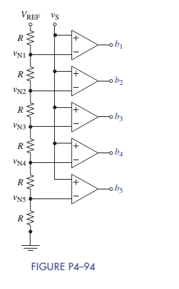
A five-bit flash ADC in Figure P4-94 uses a reference voltage of 5 V. Find the output code for the analog inputs
Expert Solution & Answer
Want to see the full answer?
Check out a sample textbook solution
Students have asked these similar questions
Hi i am trying to convert a pwm signal to a ramp signal, i have an output that currently generates around 26mA but I want a ramp current signal that will range between 0 -100mA depending on the duty cycle of the PWM .
so this means that the circuit should include an amplificator to get the current to 100mA.
can you please draw the circuit
thank you
Develop a circuit that will provide an output voltage that is -4 Vm if the input voltage is
Vmsinwt
What are 8 degenerate 2 level forms in digital electronics? How can 2 level forms be used to extend the number of inputs to gate?
Chapter 4 Solutions
EBK THE ANALYSIS AND DESIGN OF LINEAR C
Ch. 4 - Find the voltage gain vO/vS and current gain iO/ix...Ch. 4 - Prob. 4.2PCh. 4 - Prob. 4.3PCh. 4 - Prob. 4.4PCh. 4 - Find the voltage gain vO/vS in Figure P4-5.Ch. 4 - Find the voltage gain vO/vS in Figure P4-6.Ch. 4 - Find an expression for the current gain iO/iS in...Ch. 4 - Prob. 4.8PCh. 4 - Prob. 4.9PCh. 4 - Find an expression for the voltage gain vO/vs in...
Ch. 4 - Prob. 4.12PCh. 4 - In the circuit of Figure P4-13, the VCVS has of...Ch. 4 - Prob. 4.14PCh. 4 - (a) Find the Thévenin equivalent circuit that the...Ch. 4 - Prob. 4.16PCh. 4 - Prob. 4.18PCh. 4 - Prob. 4.19PCh. 4 - The circuit parameters in figure P4-21 are...Ch. 4 - The circuit parameters in Figure P4-21 are...Ch. 4 - The parameters of the transistor in Figure P4-23...Ch. 4 - Prob. 4.25PCh. 4 - Find the voltage gain of each OP AMP circuit shown...Ch. 4 - Considering simplicity and standard 10 tolerance...Ch. 4 - Two OP AMP circuits are shown in Figure P4-28....Ch. 4 - Prob. 4.29PCh. 4 - What is the range of the gain vO/vS in Figure...Ch. 4 - Using only one OP AMP, design a circuit that...Ch. 4 - Design a circuit using only one OP AMP that...Ch. 4 - Prob. 4.36PCh. 4 - For the circuit in Figure P4-37: (a) Find vO in...Ch. 4 - A young designer needed to amplify a 2-V signal by...Ch. 4 - Design two circuits to produce the following...Ch. 4 - Design a noninverting summer for five inputs with...Ch. 4 - For the circuit in Figure P4-41: Find vO in terms...Ch. 4 - The input-output relationship for a three-input...Ch. 4 - Find vo in terms of the inputs v1,v2, and v3 in...Ch. 4 - Prob. 4.44PCh. 4 - Prob. 4.45PCh. 4 - Prob. 4.46PCh. 4 - Prob. 4.47PCh. 4 - It is claimed that vO=vS when the switch is closed...Ch. 4 - Prob. 4.49PCh. 4 - Prob. 4.50PCh. 4 - Use node-voltage analysis in Figure P4-51 to show...Ch. 4 - Prob. 4.52PCh. 4 - Prob. 4.53PCh. 4 - For the block diagram of Figure P4-54: Find an...Ch. 4 - For the block diagram of Figure P4-55: Find an...Ch. 4 - For the circuit in Figure P4-56: Find vO in terms...Ch. 4 - Prob. 4.57PCh. 4 - Onan exam, students were asked to design an...Ch. 4 - Prob. 4.59PCh. 4 - For the circuit of Figure P4-60: Use node-voltage...Ch. 4 - Prob. 4.61PCh. 4 - Design a single OP AMP amplifier with a voltage...Ch. 4 - Design an OP AMP amplifier with a voltage gain of...Ch. 4 - Using a single OP AMP, design a circuit with...Ch. 4 - Design a differential amplifier with inputs v1 and...Ch. 4 - Using no more than two OP AMPs, design an OP AMP...Ch. 4 - Design a two-input noninverting summer that will...Ch. 4 - Design a three-input noninverting summer that will...Ch. 4 - Design a cascaded OP AMP circuit that will produce...Ch. 4 - Design a cascaded OP AMP circuit that will produce...Ch. 4 - Using the instrumentation amplifier shown in...Ch. 4 - Prob. 4.73PCh. 4 - Design a circuit that can produce vO=2000vTR2.6V...Ch. 4 - A requirement exists for an OP AMP circuit with...Ch. 4 - A requirement exists for an OP AMP circuit to...Ch. 4 - A particular application requires that an...Ch. 4 - Prob. 4.78PCh. 4 - The full-scale output of a six-bit DAC is 10.0 V....Ch. 4 - An R2R DAC is shown in Figure P4-80. The digital...Ch. 4 - A fifth bit is added to the R-2R DAC shown in...Ch. 4 - Prob. 4.82PCh. 4 - Prob. 4.83PCh. 4 - A small pressure transducer has the...Ch. 4 - A medical grade pressure transducer has been...Ch. 4 - The acid/alkaline balance of a fluid is measured...Ch. 4 - A photoresistor varies from 10 in bright sunlight...Ch. 4 - Your engineering firm needs an instrumentation...Ch. 4 - Prob. 4.90PCh. 4 - Prob. 4.92PCh. 4 - Prob. 4.93PCh. 4 - A five-bit flash ADC in Figure P4-94 uses a...Ch. 4 - Bipolar Power Supply Voltages The circuit in...Ch. 4 - Thermometer Design Problem There is a need to...Ch. 4 - High Bias Design Problem A particular pressure...Ch. 4 - Prob. 4.99IPCh. 4 - OP AMP Circuit Analysis and Design Find the...Ch. 4 - Instrumentation Amplifier with Alarm Strain gauges...
Knowledge Booster


Learn more about
Need a deep-dive on the concept behind this application? Look no further. Learn more about this topic, electrical-engineering and related others by exploring similar questions and additional content below.Similar questions
- Reset WED W=O W =l EhD DII W=0 Derive the following state-table Present state Next state output z2zlz0 W=0 W=1 A 000 B 001 C 010 D 011 E 100arrow_forwardVEE vcc -15V 5V Vt R2 D1 D2 R1 5000 1N4001 1N4001 3k2 Find Vt note: show your solutions for each problem.arrow_forwardConsider a PV Module with 4 solar PV cells with the Size of each 10cm x 10cm are connected in Parallel. If we connect a lamp load of 2W across this module, choose the correct statement for the above PV Module. (Assume necessary data) a. The output voltage is 0.5V, the output current is 2A b. The output voltage is 0.5V, the output current is 4A c. The output voltage is 2V, the output current is 2A d. The output voltage is 2V, the output current is 4Aarrow_forward
- Given the circuit provided in Figure 4-30 (p. 194) and the fabrication parameters provided, find ID and VDS. VBias = 3.8V, VDD = 5V, RD= 1kΩ, RS = 1kΩ, Vt = 0.3V, kn = 100uA/V2. (NOTE: use Wolfram Alpha Equation Solver.) (b) Design a voltage divider circuit to create the bias voltage using resistors R1 and R2. Let the current through the voltage divider be in the range of 1mA to 10mA.arrow_forwardIf you want to convert a 2 V DC signal to 10 V DC signal, then the values of R, and R2 should be ww R1=10k2, R2=2kN R1=2kQ, R2=10KN R1=10kN, R2=5kN R1=5k2, R2=10KNarrow_forward10 kN and R 30 kn. Assume that the op- 4-23. Consider the circuit of Figure P4-11 with R¡ amp slew rate is 0.5 V/us. Calculate the rise time TSR due to the slew rate when the input is a pulse that changes from zero to each of the following values: a. 0.2 V b. 1 V c. 3 V SR = type your answer... a) Tsr = b) Tsr= c) Tsr = type your answer... type your answer... type your answer... FIGURE P4-11 R₁ ww + Rfiq ww + Voarrow_forward
- Q2. A Speedo meter has a static error of 2 RPM with an accuracy of 98.12%, then calculate the following. i. True Value ) ii. % Errorarrow_forwardV - Design an ADC circuit using OPAMP (using weighted resistors)arrow_forwardConnect a thermistor (Resistance=500 – 1% per °C) in a bridge (power supply =8V) with an instrumentation amplifier (IA '521), and an inverting amplifier, and design so that output =4V at 30 C. Constraints: Use any value of resistors in the range 1K-100Karrow_forward
- Design a clamper circuit as follows:arrow_forwardVoltage Zener is used in the circuit below and the load current is to vary from 12 to 100 mA. Find the value of series resistance R and the range of load resistance to maintain a voltage of 7.2 V across the load. The input voltage is constant at 12V and the minimum Zener current is 10 mA. ... IL R Iz Eo RL Vz E, = 12 Varrow_forwardThe three resistors are: R, = R3 = R4 = 100 2 The strain gauge (RsG) with the following characteristics is used: a nominal resistance of 100 Q and an increase of 0.3 2/ Newton from a measured quantity of 0 to 10 N. A maximum current of 25 mA is used avoid damaging the strain gauge due to heating. Determine the maximum DC source allowed. What is the range of the output voltages for 0 to 10 Newton?arrow_forward
arrow_back_ios
SEE MORE QUESTIONS
arrow_forward_ios
Recommended textbooks for you
 Introductory Circuit Analysis (13th Edition)Electrical EngineeringISBN:9780133923605Author:Robert L. BoylestadPublisher:PEARSON
 Delmar's Standard Textbook Of ElectricityElectrical EngineeringISBN:9781337900348Author:Stephen L. HermanPublisher:Cengage Learning
 Programmable Logic ControllersElectrical EngineeringISBN:9780073373843Author:Frank D. PetruzellaPublisher:McGraw-Hill Education
 Fundamentals of Electric CircuitsElectrical EngineeringISBN:9780078028229Author:Charles K Alexander, Matthew SadikuPublisher:McGraw-Hill Education
 Electric Circuits. (11th Edition)Electrical EngineeringISBN:9780134746968Author:James W. Nilsson, Susan RiedelPublisher:PEARSON
 Engineering ElectromagneticsElectrical EngineeringISBN:9780078028151Author:Hayt, William H. (william Hart), Jr, BUCK, John A.Publisher:Mcgraw-hill Education,
Introductory Circuit Analysis (13th Edition)
Electrical Engineering
ISBN:9780133923605
Author:Robert L. Boylestad
Publisher:PEARSON
Delmar's Standard Textbook Of Electricity
Electrical Engineering
ISBN:9781337900348
Author:Stephen L. Herman
Publisher:Cengage Learning
Programmable Logic Controllers
Electrical Engineering
ISBN:9780073373843
Author:Frank D. Petruzella
Publisher:McGraw-Hill Education
Fundamentals of Electric Circuits
Electrical Engineering
ISBN:9780078028229
Author:Charles K Alexander, Matthew Sadiku
Publisher:McGraw-Hill Education
Electric Circuits. (11th Edition)
Electrical Engineering
ISBN:9780134746968
Author:James W. Nilsson, Susan Riedel
Publisher:PEARSON
Engineering Electromagnetics
Electrical Engineering
ISBN:9780078028151
Author:Hayt, William H. (william Hart), Jr, BUCK, John A.
Publisher:Mcgraw-hill Education,
Electrical Engineering: Ch 5: Operational Amp (2 of 28) Inverting Amplifier-Basic Operation; Author: Michel van Biezen;https://www.youtube.com/watch?v=x2xxOKOTwM4;License: Standard YouTube License, CC-BY