SHIGLEY'S MECH.ENGINEERING DESIGN-EBK>I
10th Edition
ISBN: 9781259489563
Author: BUDYNAS
Publisher: INTER MCG
bartleby

Concept explainers

bartleby

Videos

Question
Book Icon
Chapter 4, Problem 57P
To determine

The required pair of structural steel channels.

Expert Solution & Answer
Check Mark

Answer to Problem 57P

The required pair of structural steel channels is 5in×6.7lbf/ft.

Explanation of Solution

The Figure (1) shows the free body diagram of the beam.
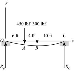
SHIGLEY'S MECH.ENGINEERING DESIGN-EBK>I, Chapter 4, Problem 57P

Figure (1)

Here, the reaction force at point O is RO and at the point C is RC.

Write the net moment at point O.

    RC×l(F1×a)(F2×b)=0                                                    (I)

Here, the reaction force at point C is RC, the length of the beam is l, the reaction force at point A is F1, the distance between the point Aand point O is a, the reaction force at point B is F2, the distance between the point Band point O is b.

Write the expression for the net force on the beam.

    RO+RCF1F2=0                                                            (II)

Here, the net reaction force at point O is RO.

Refer to Table 3-1 “Singularity (Macaulay) functions”.

Write the expression for load intensity acting on the beam.

    q=ROx1F1xa1F2xb1+RCxl1   (III)

Here, the load intensity on the beam is q, the distance from the left end is x.

Write the expression for the moment.

    M=qdx                                                                     (IV)

Here, the net bending moment is M.

Substitute the value from Equation (III) to Equation (IV).

    M=ROx1F1xa1F2xb1+RCxl1=ROx1F1xa1F2xb1+RCxl1    (V)

Write the equation for the deflection across the beam.

    EId2ydx2=M      (VI)

Here, the modulus of elasticity is E, the area moment of inertia is I and the deflection is y.

Substitute the value from Equation (V) to Equation (VI).

    EId2ydx2=ROx1F1xa1F2xb1+RCxl1             (VII)

Integrate Equation (VII) with respect to x.

    EIdydx=RO2x2F12xa2F22xb2+RC2xl2+C1   (VIII)

Integrate the Equation (IX) with respect to x.

    EIy=RO6x3F16xa3F26xb3+RC6xl3+C1x+C2 (IX)

Write the expression for the bending stress in the beam.

    σmax=MmaxcI11                                                                                (X)

Here, the bending stress is σ, the deflection caused by two channels is I11 and the distance between the edge and neutral axis is c.

Write the expression for deflection at the midspan using similar triangles.

    ymid=II11(12)                                                                    (XI)

Here, the deflection at the mid-span is ymid.

Write the expression for the area moment of inertia.

    I=2I11                                                                                       (XII)

Here, the moment of inertia of single channel is I1-1.

Conclusion:

Refer to Table A-5 “Physical Constants of Materials”; obtain the properties of modulus of elasticity for carbon steel as, 30×106psi

Substitute 450lbf for F1, 300lbf for F2, 20ft for l, 6ft for a and 10ft for b in Equation (I).

    [{RC×(20ft)(12in1ft)}{(450lbf)×(6ft)(12in1ft)}{(300lbf)×(10ft)(12in1ft)}]=0RC=68400lbfin240inRC=285lbf

Substitute 450lbf for F1, 300lbf for F2 and 285lbf for RC in Equation (I).

    RO+285lbf450lbf300lbf=0RO=465lbf

Substitute 0 for x and 0 for y in Equation (IX).

    EI×0=RO60300+0+C1×0+C2C2=0

Substitute 465lbf for RO, 10ft for x,450lbf for F1, 300lbf for F2, 285lbf for RC, 6ft for a and 10ft for b in Equation (V).

    Mmax=[(465lbf)(10ft)1(450lbf)(10ft)(6ft)1(300lbf)(10ft)(10ft)1+0]=[(465lbf)(10ft)(12in1ft)1(450lbf)(10ft)(12in1ft)(6ft)(12in1ft)1(300lbf)(10ft)(12in1ft)(10ft)(12in1ft)1+0]=55800lbfin21600lbfin=34.2×10³lbfin

Substitute 240in for x, 0 for C2,450lbf for F1, 300lbf for F2, 285lbf for RC, 6ft for a, 10ft for b, 20ft for l and 0 for y in Equation (IX).

    EI×0=[465lbf6(20ft)3450lbf6(20ft)(6ft)3300lbf6(20ft)(10ft)3+RC6(20ft)(20ft)3+C1×(20ft)+0]0=[465lbf6(20ft)(12in1ft)3450lbf6(20ft)(12in1ft)(6ft)(12in1ft)3300lbf6(20ft)(12in1ft)(10ft)(12in1ft)3+RC6(20ft)(12in1ft)(20ft)(12in1ft)3+C1×(20ft)(12in1ft)+0]C1=77.5lbf×(240in)3+75lbf×(168in)3+50lbf×(120in)3240C1=2.622×10⁶lbfin2

Substitute 0 for C2 and 2.622×10⁶lbfin2 for C1 in Equation (IX).

    EIy=[RO6x3F16xa3F26xb3+RC6xl3(2.622×10⁶lbfin2)x]y=1EI[RO6x3F16xa3F26xb3+RC6xl3(2.622×10⁶lbfin2)x]   (XIII)

Substitute 465lbf for RO, 120in for x,450lbf for F1, 300lbf for F2, 285lbf for RC, 6ft for a, 10ft for b, 20ft for l, 30×106psi for E, 2.622×10⁶lbfin2 for C1 and 0.5in for y in Equation (XIII).

    0.5=1(30×106)I[465lbf6120in3450lbf6120in(6ft)3300lbf6120in(10ft)3+0(2.622×10⁶lbfin2)×120in]0.5=1(30×106)I[465lbf6120in3450lbf6120in(6ft)(12in1ft)3'300lbf6120in(10ft)(12in1ft)3+0(2.622×10⁶lbfin2)×120in]I=12.60in4

The obtain value of second area of moment is 12.60in4. Select and check the results for a value of second area of moment that is greater than the obtain value for the deflection to maintain at the same level of 0.5in.

Refer to Table A-7 “Properties of StructuralSteel Channels”. Select two steel channels of 5in×6.7lbf/ft.

    I11=7.49in4

Substitute 7.49in4 for I11 in Equation (XII).

    I=2×7.49in4=14.98in4

Substitute 34.2×10³lbfin for Mmax, 2.5in for c and 14.98in4 for I11 in Equation (X).

    σmax=34.2×10³lbfin×2.5in14.98in4=(5710psi)(1kpsi1000psi)=5.7kpsi

Substitute 14.98in4 for I11, 12.60in4 for I in Equation (XI).

    ymid=12.60in414.98in4(12)=0.421

Since the deflection at the midspan and the maximum stress in the beam is lying within the limits, so the selected pair of channels are significant.

Thus, the pair of structural steel channels is 5in×6.7lbf/ft.

Want to see more full solutions like this?

Subscribe now to access step-by-step solutions to millions of textbook problems written by subject matter experts!

Chapter 4 Solutions

SHIGLEY'S MECH.ENGINEERING DESIGN-EBK>I

Ch. 4 - A simply supported beam loaded by two forces is...Ch. 4 - Using superposition, find the deflection of the...Ch. 4 - A rectangular steel bar supports the two...Ch. 4 - An aluminum tube with outside diameter of 2 in and...Ch. 4 - The cantilever shown in the figure consists of two...Ch. 4 - Using superposition for the bar shown, determine...Ch. 4 - A simply supported beam has a concentrated moment...Ch. 4 - Prob. 18PCh. 4 - Using the results of Prob. 418, use superposition...Ch. 4 - Prob. 20PCh. 4 - Consider the uniformly loaded simply supported...Ch. 4 - Prob. 22PCh. 4 - Prob. 23PCh. 4 - Prob. 24PCh. 4 - Prob. 25PCh. 4 - Prob. 26PCh. 4 - Prob. 27PCh. 4 - Prob. 28PCh. 4 - 429 to 434 For the steel countershaft specified in...Ch. 4 - Prob. 30PCh. 4 - Prob. 31PCh. 4 - Prob. 32PCh. 4 - For the steel countershaft specified in the table,...Ch. 4 - For the steel countershaft specified in the table,...Ch. 4 - Prob. 35PCh. 4 - Prob. 36PCh. 4 - Prob. 37PCh. 4 - Prob. 38PCh. 4 - Prob. 39PCh. 4 - Prob. 40PCh. 4 - The cantilevered handle in the figure is made from...Ch. 4 - Prob. 42PCh. 4 - The cantilevered handle in Prob. 384, p. 154, is...Ch. 4 - A flat-bed trailer is to be designed with a...Ch. 4 - The designer of a shaft usually has a slope...Ch. 4 - Prob. 46PCh. 4 - If the diameter of the steel beam shown is 1.25...Ch. 4 - For the beam of Prob. 4-47, plot the magnitude of...Ch. 4 - Prob. 49PCh. 4 - 4-50 and 4-51 The figure shows a rectangular...Ch. 4 - and 451 the ground at one end and supported by a...Ch. 4 - The figure illustrates a stepped torsion-bar...Ch. 4 - Consider the simply supported beam 5 with a center...Ch. 4 - Prob. 54PCh. 4 - Prob. 55PCh. 4 - Solve Prob. 410 using singularity functions. Use...Ch. 4 - Prob. 57PCh. 4 - Prob. 58PCh. 4 - Prob. 59PCh. 4 - Solve Prob. 413 using singularity functions. Since...Ch. 4 - Prob. 61PCh. 4 - Solve Prob. 419 using singularity functions to...Ch. 4 - Using singularity functions, write the deflection...Ch. 4 - Determine the deflection equation for the...Ch. 4 - Use Castiglianos theorem to verify the maximum...Ch. 4 - Use Castiglianos theorem to verify the maximum...Ch. 4 - Solve Prob. 415 using Castiglianos theorem.Ch. 4 - Solve Prob. 452 using Castiglianos theoremCh. 4 - Determine the deflection at midspan for the beam...Ch. 4 - Using Castiglianos theorem, determine the...Ch. 4 - Solve Prob. 441 using Castiglianos theorem. Since...Ch. 4 - Solve Prob. 442 using Castiglianos theorem.Ch. 4 - The cantilevered handle in Prob. 384 is made from...Ch. 4 - Solve Prob. 450 using Castiglianos theorem.Ch. 4 - Solve Prob. 451 using Castiglianos theorem.Ch. 4 - The steel curved bar shown has a rectangular cross...Ch. 4 - Repeat Prob. 476 to find the vertical deflection...Ch. 4 - For the curved steel beam shown. F = 6.7 kips....Ch. 4 - A steel piston ring has a mean diameter of 70 mm....Ch. 4 - For the steel wire form shown, use Castiglianos...Ch. 4 - 4-81 and 4-82 The part shown is formed from a...Ch. 4 - 4-81 and 4-82 The part shown is formed from a...Ch. 4 - Repeat Prob. 481 for the vertical deflection at...Ch. 4 - Repeat Prob. 482 for the vertical deflection at...Ch. 4 - A hook is formed from a 2-mm-diameter steel wire...Ch. 4 - The figure shows a rectangular member OB, made...Ch. 4 - Prob. 87PCh. 4 - For the wire form shown, determine the deflection...Ch. 4 - Prob. 89PCh. 4 - Prob. 90PCh. 4 - Prob. 91PCh. 4 - Prob. 92PCh. 4 - Solve Prob. 492 using Castiglianos method and...Ch. 4 - An aluminum step bar is loaded as shown. (a)...Ch. 4 - The steel shaft shown in the figure is subjected...Ch. 4 - Repeat Prob. 495 with the diameters of section OA...Ch. 4 - The figure shows a 12- by 1-in rectangular steel...Ch. 4 - For the beam shown, determine the support...Ch. 4 - Solve Prob. 498 using Castiglianos theorem and...Ch. 4 - Consider beam 13 in Table A9, but with flexible...Ch. 4 - Prob. 101PCh. 4 - The steel beam ABCD shown is simply supported at C...Ch. 4 - Prob. 103PCh. 4 - A round tubular column has outside and inside...Ch. 4 - For the conditions of Prob. 4104, show that...Ch. 4 - Link 2, shown in the figure, is 25 mm wide, has...Ch. 4 - Link 3, shown schematically in the figure, acts as...Ch. 4 - The hydraulic cylinder shown in the figure has a...Ch. 4 - The figure shows a schematic drawing of a...Ch. 4 - If drawn, a figure for this problem would resemble...Ch. 4 - Design link CD of the hand-operated toggle press...Ch. 4 - Find the maximum values of the spring force and...Ch. 4 - As shown in the figure, the weight W1 strikes W2...Ch. 4 - Part a of the figure shows a weight W mounted...
Knowledge Booster
Background pattern image
Mechanical Engineering
Learn more about
Need a deep-dive on the concept behind this application? Look no further. Learn more about this topic, mechanical-engineering and related others by exploring similar questions and additional content below.
Similar questions
SEE MORE QUESTIONS
Recommended textbooks for you
Text book image
Mechanics of Materials (MindTap Course List)
Mechanical Engineering
ISBN:9781337093347
Author:Barry J. Goodno, James M. Gere
Publisher:Cengage Learning
EVERYTHING on Axial Loading Normal Stress in 10 MINUTES - Mechanics of Materials; Author: Less Boring Lectures;https://www.youtube.com/watch?v=jQ-fNqZWrNg;License: Standard YouTube License, CC-BY