
SHIGLEY'S MECH.ENGINEERING DESIGN-EBK>I
10th Edition
ISBN: 9781259489563
Author: BUDYNAS
Publisher: INTER MCG
expand_more
expand_more
format_list_bulleted
Concept explainers
Videos
Textbook Question
Chapter 4, Problem 47P
If the diameter of the steel beam shown is 1.25 in. determine the deflection of the beam at x = 8 in.
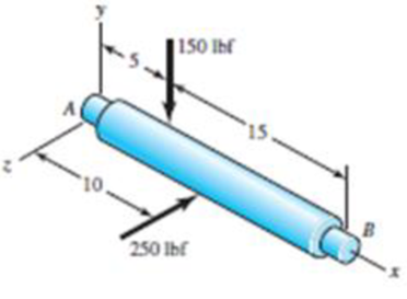
Problem 4-47
Dimensions in inches
Expert Solution & Answer
Want to see the full answer?
Check out a sample textbook solution
Chapter 4 Solutions
SHIGLEY'S MECH.ENGINEERING DESIGN-EBK>I
Ch. 4 - The figure shows a torsion bar OA fixed at O,...Ch. 4 - For Prob. 41, if the simple support at point A...Ch. 4 - A torsion-bar spring consists of a prismatic bar,...Ch. 4 - An engineer is forced by geometric considerations...Ch. 4 - A bar in tension has a circular cross section and...Ch. 4 - Prob. 6PCh. 4 - Prob. 7PCh. 4 - Derive the equations given for beam 2 in Table A9...Ch. 4 - Derive the equations given for beam 5 in Table A9...Ch. 4 - The figure shows a cantilever consisting of steel...
Ch. 4 - A simply supported beam loaded by two forces is...Ch. 4 - Using superposition, find the deflection of the...Ch. 4 - A rectangular steel bar supports the two...Ch. 4 - An aluminum tube with outside diameter of 2 in and...Ch. 4 - The cantilever shown in the figure consists of two...Ch. 4 - Using superposition for the bar shown, determine...Ch. 4 - A simply supported beam has a concentrated moment...Ch. 4 - Prob. 18PCh. 4 - Using the results of Prob. 418, use superposition...Ch. 4 - Prob. 20PCh. 4 - Consider the uniformly loaded simply supported...Ch. 4 - Prob. 22PCh. 4 - Prob. 23PCh. 4 - Prob. 24PCh. 4 - Prob. 25PCh. 4 - Prob. 26PCh. 4 - Prob. 27PCh. 4 - Prob. 28PCh. 4 - 429 to 434 For the steel countershaft specified in...Ch. 4 - Prob. 30PCh. 4 - Prob. 31PCh. 4 - Prob. 32PCh. 4 - For the steel countershaft specified in the table,...Ch. 4 - For the steel countershaft specified in the table,...Ch. 4 - Prob. 35PCh. 4 - Prob. 36PCh. 4 - Prob. 37PCh. 4 - Prob. 38PCh. 4 - Prob. 39PCh. 4 - Prob. 40PCh. 4 - The cantilevered handle in the figure is made from...Ch. 4 - Prob. 42PCh. 4 - The cantilevered handle in Prob. 384, p. 154, is...Ch. 4 - A flat-bed trailer is to be designed with a...Ch. 4 - The designer of a shaft usually has a slope...Ch. 4 - Prob. 46PCh. 4 - If the diameter of the steel beam shown is 1.25...Ch. 4 - For the beam of Prob. 4-47, plot the magnitude of...Ch. 4 - Prob. 49PCh. 4 - 4-50 and 4-51 The figure shows a rectangular...Ch. 4 - and 451 the ground at one end and supported by a...Ch. 4 - The figure illustrates a stepped torsion-bar...Ch. 4 - Consider the simply supported beam 5 with a center...Ch. 4 - Prob. 54PCh. 4 - Prob. 55PCh. 4 - Solve Prob. 410 using singularity functions. Use...Ch. 4 - Prob. 57PCh. 4 - Prob. 58PCh. 4 - Prob. 59PCh. 4 - Solve Prob. 413 using singularity functions. Since...Ch. 4 - Prob. 61PCh. 4 - Solve Prob. 419 using singularity functions to...Ch. 4 - Using singularity functions, write the deflection...Ch. 4 - Determine the deflection equation for the...Ch. 4 - Use Castiglianos theorem to verify the maximum...Ch. 4 - Use Castiglianos theorem to verify the maximum...Ch. 4 - Solve Prob. 415 using Castiglianos theorem.Ch. 4 - Solve Prob. 452 using Castiglianos theoremCh. 4 - Determine the deflection at midspan for the beam...Ch. 4 - Using Castiglianos theorem, determine the...Ch. 4 - Solve Prob. 441 using Castiglianos theorem. Since...Ch. 4 - Solve Prob. 442 using Castiglianos theorem.Ch. 4 - The cantilevered handle in Prob. 384 is made from...Ch. 4 - Solve Prob. 450 using Castiglianos theorem.Ch. 4 - Solve Prob. 451 using Castiglianos theorem.Ch. 4 - The steel curved bar shown has a rectangular cross...Ch. 4 - Repeat Prob. 476 to find the vertical deflection...Ch. 4 - For the curved steel beam shown. F = 6.7 kips....Ch. 4 - A steel piston ring has a mean diameter of 70 mm....Ch. 4 - For the steel wire form shown, use Castiglianos...Ch. 4 - 4-81 and 4-82 The part shown is formed from a...Ch. 4 - 4-81 and 4-82 The part shown is formed from a...Ch. 4 - Repeat Prob. 481 for the vertical deflection at...Ch. 4 - Repeat Prob. 482 for the vertical deflection at...Ch. 4 - A hook is formed from a 2-mm-diameter steel wire...Ch. 4 - The figure shows a rectangular member OB, made...Ch. 4 - Prob. 87PCh. 4 - For the wire form shown, determine the deflection...Ch. 4 - Prob. 89PCh. 4 - Prob. 90PCh. 4 - Prob. 91PCh. 4 - Prob. 92PCh. 4 - Solve Prob. 492 using Castiglianos method and...Ch. 4 - An aluminum step bar is loaded as shown. (a)...Ch. 4 - The steel shaft shown in the figure is subjected...Ch. 4 - Repeat Prob. 495 with the diameters of section OA...Ch. 4 - The figure shows a 12- by 1-in rectangular steel...Ch. 4 - For the beam shown, determine the support...Ch. 4 - Solve Prob. 498 using Castiglianos theorem and...Ch. 4 - Consider beam 13 in Table A9, but with flexible...Ch. 4 - Prob. 101PCh. 4 - The steel beam ABCD shown is simply supported at C...Ch. 4 - Prob. 103PCh. 4 - A round tubular column has outside and inside...Ch. 4 - For the conditions of Prob. 4104, show that...Ch. 4 - Link 2, shown in the figure, is 25 mm wide, has...Ch. 4 - Link 3, shown schematically in the figure, acts as...Ch. 4 - The hydraulic cylinder shown in the figure has a...Ch. 4 - The figure shows a schematic drawing of a...Ch. 4 - If drawn, a figure for this problem would resemble...Ch. 4 - Design link CD of the hand-operated toggle press...Ch. 4 - Find the maximum values of the spring force and...Ch. 4 - As shown in the figure, the weight W1 strikes W2...Ch. 4 - Part a of the figure shows a weight W mounted...
Knowledge Booster


Learn more about
Need a deep-dive on the concept behind this application? Look no further. Learn more about this topic, mechanical-engineering and related others by exploring similar questions and additional content below.Similar questions
- -3 The deflection curve for a simple beam AB (see figure) is given by v=q0x360LEI(7L410L2x2+3x4) Describe the load acting on the beam.arrow_forwardA seesaw weighing 3 lb/ft of length is occupied by two children, each weighing 90 lb (see figure). The center of gravity of each child is 8 ft from the fulcrum. The board is 19 ft long, 8 in. wide, and 1.5 in. thick. What is the maximum bending stress in the board?arrow_forwardThe column shown in the figure is fixed at the base and free at the upper end. A compressive load P acts at the top of the column with an eccentricity e from the axis of the column. Beginning with the differential equation of the deflection curve, derive formulas for the maximum deflection S of the column and the maximum bending moment Mmaxin the column.arrow_forward
- The cantilever beam ACB shown in the figure has moments of inertia /, and I{in parts AC and CB, respectively. Using the method of superposition, determine the deflection 8Bat the free end due to the load P. Determine the ratio r of the deflection 8Bto the deflection S:at the free end of a prismatic cantilever with moment of inertia /] carrying the same load. Plot a graph of the deflection ratio r versus the ratio 12 //L of the moments of inertia. (Let /, II- vary from I to 5.)arrow_forwardObtain a formula for the ratio c/maxof the deflection at the midpoint to the maximum deflection for a simple beam supporting a concentrated load P (see figure). From the formula, plot a graph of c/max versus the ratio a/L that defines the position of the load (0.5 < a/L < ) What conclusion do you draw from the graph? (Use the formulas of Example 9-3.)arrow_forward-6 Calculate the maximum deflection of a uniformly loaded simple beam if the span length L = 2.0 m, the intensity of the uniform load q = 2.0 kN/m, and the maximum bending stress = 60 MPa, The cross section of the beam is square, and the material is aluminum having modulus of elasticity E = 70 GPa. (Use the formulas of Example 9-1.)arrow_forward
- Plot the load-deflection diagram for a pinned-end column with eccentric axial loads (see figure) if the eccentricity e of the load is 5 mm and the column has a length L = 3.6 m, moment of inertia L = 9,0 × 106 mm4, and modulus of elasticity E = 210 GPa. Note: Plot the axial load as ordinate and the deflection at the midpoint as abscissa.arrow_forwardThe cantilever beam AB shown in the figure has an extension BCD attached to its free end. A force P acts at the end of the extension. Find the ratio aiL so that the vertical deflection of point B will be zero. Find the ratio aiL so that the angle of rotation at point B will be zero.arrow_forwardA cantilever beam model is often used to represent micro-clectrical-mechanical systems (MEMS) (sec figure}. The cantilever beam is made of polysilicon (E = 150 GPa) and is subjected to an electrostatic moment M applied at the end of the cantilever beam. 1 f dimensions arc h — 2 [im, h — 4 ^m, and L = 520 ^mt find expressions for the tip deflection and rotation of the cantilever beam in terms of moment M.arrow_forward
- A horizontal load P acts at end C of the bracket ABC shown in the figure. Determine the deflection 6Cof point C. Determine the maximum upward deflection 8 of member AB. Note: Assume that the flexural rigidity EI is constant throughout the frame. Also, disregard the effects of axial deformations and consider only the effects of bending due to the load P.arrow_forward-33 Find the horizontal deflection hand verti cal deflection vat the free end C of the frame ABC shown in the figure. (The flexural rigidity EI is con stant throughout the frame.) Note: Disregard the effects of axial deformations and consider only the effects of bending due to the load P.arrow_forwardA temporary wood flume serving as a channel for irrigation water is shown in the figure. The vertical boards forming the sides of the flume are sunk in the ground, which provides a fixed support. The top of the flume is held by tic rods that are tightened so that there is no deflection of the boards at that point. Thus, the vertical boards may be modeled as a beam AB, supported and loaded as shown in the last part of the figure. Assuming that the thickness t of the boards is 1,5 in., the depth d of the water is 40 in., and the height h to the tie rods is 50 in., what is the maximum bending stress in the boards? Hint: The numerically largest bending moment occurs at the fixed support.arrow_forward
arrow_back_ios
SEE MORE QUESTIONS
arrow_forward_ios
Recommended textbooks for you
 Mechanics of Materials (MindTap Course List)Mechanical EngineeringISBN:9781337093347Author:Barry J. Goodno, James M. GerePublisher:Cengage Learning
Mechanics of Materials (MindTap Course List)
Mechanical Engineering
ISBN:9781337093347
Author:Barry J. Goodno, James M. Gere
Publisher:Cengage Learning
Solids: Lesson 53 - Slope and Deflection of Beams Intro; Author: Jeff Hanson;https://www.youtube.com/watch?v=I7lTq68JRmY;License: Standard YouTube License, CC-BY