
PROGRAMMABLE LOGIC CONTROLLERS-ACCESS
5th Edition
ISBN: 9781259680915
Author: Petruzella
Publisher: MCG
expand_more
expand_more
format_list_bulleted
Concept explainers
Question
Chapter 4, Problem 5RQ
Program Plan Intro
Logic gate:
- Logic gate is an electronic circuit that is used to take logical decisions based on the input.
- It contains one or more number of inputs and one output.
- The working of logic gate is based on the binary principle that has two states either logic 0 or logic 1.
- The output of logic gate is produced when it satisfies any of its logic conditions.
- The logic condition depends upon the type of the gates and the number of inputs.
- The primary logic gates include AND, OR and NOT and the combinations of these gates are used to implement any of the other logic gates.
AND gate:
- The AND gate refers to a logic gate whose output will be HIGH only when all the inputs are HIGH.
- The output of AND gate will be LOW when any one of its input is LOW.
- The symbol to represent AND gate is given below:
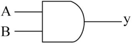
- The truth table for AND gate is as follows:
| INPUT A | INPUT B | OUTPUT Y |
| 0 | 0 | 0 |
| 0 | 1 | 0 |
| 1 | 0 | 0 |
| 1 | 1 | 1 |
OR gate:
- The OR gate refers to a logic gate whose output will be HIGH when any one of its inputs are HIGH.
- The output of AND gate will be LOW when both the inputs are LOW.
- The symbol to represent OR gate is given below:
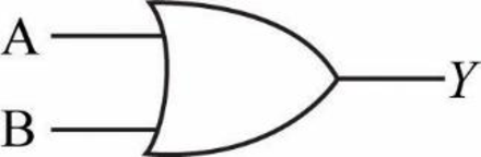
- The truth table for OR gate is as follows:
| INPUT A | INPUT B | OUTPUT Y |
| 0 | 0 | 0 |
| 0 | 1 | 1 |
| 1 | 0 | 1 |
| 1 | 1 | 1 |
NOT gate:
- The NOT gate refers to a logic gate whose output will be HIGH when it’s input is LOW and whose output will be LOW when it’s input is HIGH.
- The symbol to represent NOT gate is given below:
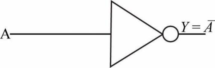
- The truth table for NOT gate is as follows:
| INPUT A | OUTPUT Y |
| 0 | 1 |
| 1 | 0 |
Explanation of Solution
b.
Logic gate circuit:
The logic gate circuit for the given relay ladder diagram is as follows.
Explanation:
In the above given logic gate circuit,
- The input “C” is connected to logic NOT gate and the corresponding output will be “
- Then the inputs “A”, “B”, “
- Now, the resultant along with the other input “D” is connected to a logic AND gate whose output will be
Expert Solution & Answer
Want to see the full answer?
Check out a sample textbook solution
Students have asked these similar questions
Write the Boolean equation and then complete the timing diagram at W, X,
Y, Z for the logic circuits shown in figure without gate delays.
Create a Boolean expression for the logic circuit shown in the diagram below?
Find the Boolean equation for the logic circuit shown in Figure 5-5.
Chapter 4 Solutions
PROGRAMMABLE LOGIC CONTROLLERS-ACCESS
Knowledge Booster


Learn more about
Need a deep-dive on the concept behind this application? Look no further. Learn more about this topic, computer-science and related others by exploring similar questions and additional content below.Similar questions
- Write the Boolean expression (in Sum of Products form) for the logic circuit that will have a 1 output when X = 0, Y = 0, Z = 1 and X = 1, Y = 1, Z = 0, and a zero (0) output for all other input states. Draw the logic diagram for this circuit.arrow_forwardDesign a logic circuit with input signal A, control input B, and outputs X and Y to operate as follows: When B = 1, output X will follow input A, and output Y will be 0. When B = 0, output X will be 0, and output Y will follow input A.arrow_forwardFind the digital logic circuit output Y as shown above. Y is the output and the three inputs are A, B and C. Computerarrow_forward
- For the Boolean function F = x y ′ z + x ′ y ′ z + w ′ x y + w x ′ y + w x y. Draw the logic diagram from the simplified expression, and compare the total number of gates with the diagram of part "For the Boolean function F = x y ′ z + x ′ y ′ z + w ′ x y + w x ′ y + w x y. Draw the logic diagram, using the original Boolean expression.".arrow_forwardWrite the truth table for this logic circuitarrow_forwardFind the digital logic circuit output Y as shown above. Y is the output and the three inputs are A, B and C.arrow_forward
- Draw the logic diagram of the digital circuit specified by the following Verilog description:arrow_forwardA sequential circuit has two JK flip-flops, one input x, and one output y. The logic diagram of the circuit is shown below. Derive the state table and state diagram of the circuit.arrow_forwardThe output of the logic circuit is ... A exnor B A exor B A or B A and Barrow_forward
- What type of logic circuit is represented by the figure 4 shown belowarrow_forwardfind the Boolean Expressioncorresponding to each of the logic circuits shown in figure (4)arrow_forwardUse Boolean algebra to simplify the following expression, then draw a logic gate circuit for the simplified expression: A’B’C’+A’B’C+AB’C’+AB’Carrow_forward
arrow_back_ios
SEE MORE QUESTIONS
arrow_forward_ios
Recommended textbooks for you
 Database System ConceptsComputer ScienceISBN:9780078022159Author:Abraham Silberschatz Professor, Henry F. Korth, S. SudarshanPublisher:McGraw-Hill Education
 Starting Out with Python (4th Edition)Computer ScienceISBN:9780134444321Author:Tony GaddisPublisher:PEARSON
 Digital Fundamentals (11th Edition)Computer ScienceISBN:9780132737968Author:Thomas L. FloydPublisher:PEARSON
 C How to Program (8th Edition)Computer ScienceISBN:9780133976892Author:Paul J. Deitel, Harvey DeitelPublisher:PEARSON
 Database Systems: Design, Implementation, & Manag...Computer ScienceISBN:9781337627900Author:Carlos Coronel, Steven MorrisPublisher:Cengage Learning
 Programmable Logic ControllersComputer ScienceISBN:9780073373843Author:Frank D. PetruzellaPublisher:McGraw-Hill Education
Database System Concepts
Computer Science
ISBN:9780078022159
Author:Abraham Silberschatz Professor, Henry F. Korth, S. Sudarshan
Publisher:McGraw-Hill Education
Starting Out with Python (4th Edition)
Computer Science
ISBN:9780134444321
Author:Tony Gaddis
Publisher:PEARSON
Digital Fundamentals (11th Edition)
Computer Science
ISBN:9780132737968
Author:Thomas L. Floyd
Publisher:PEARSON
C How to Program (8th Edition)
Computer Science
ISBN:9780133976892
Author:Paul J. Deitel, Harvey Deitel
Publisher:PEARSON
Database Systems: Design, Implementation, & Manag...
Computer Science
ISBN:9781337627900
Author:Carlos Coronel, Steven Morris
Publisher:Cengage Learning
Programmable Logic Controllers
Computer Science
ISBN:9780073373843
Author:Frank D. Petruzella
Publisher:McGraw-Hill Education