
PROGRAMMABLE LOGIC CONTROLLERS-ACCESS
5th Edition
ISBN: 9781259680915
Author: Petruzella
Publisher: MCG
expand_more
expand_more
format_list_bulleted
Concept explainers
Question
Chapter 4, Problem 3P
Program Plan Intro
Logic gate:
- Logic gate is an electronic circuit that is used to perform logic decisions based on the input.
- It contains one or more number of inputs and one output.
- The working of logic gate is based on the binary principle that has two states either logic 0 or logic 1.
- The output of logic gate is produced when it satisfies any of its logic conditions.
- The logic condition depends upon the type of the gates and the number of inputs.
- The primary logic gates include AND, OR, and NOT. The combinations of these gates are used to implement any of the other logic gates.
AND gate:
- The AND gate refers to a logic gate whose output will be HIGH only when all the inputs are HIGH.
- The output of AND gate will be LOW when any one of its input will be LOW.
- The symbol to represent AND gate is given below:
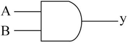
- The truth table for AND gate is as follows:
| INPUT A | INPUT B | OUTPUT Y |
| 0 | 0 | 0 |
| 0 | 1 | 0 |
| 1 | 0 | 0 |
| 1 | 1 | 1 |
NOR gate:
- NOR gate performs the inverse operation of OR gate.
- The NOR gate refers to a logic gate whose output will be HIGH only when all the inputs are LOW.
- The output of NOR gate will be LOW when any one of its input will be HIGH.
- The symbol to represent NOR gate is given below:
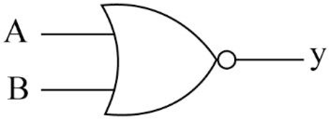
- The truth table for NOR gate is as follows:
| INPUT A | INPUT B | OUTPUT Y |
| 0 | 0 | 1 |
| 0 | 1 | 0 |
| 1 | 0 | 0 |
| 1 | 1 | 0 |
Expert Solution & Answer

Trending nowThis is a popular solution!

Students have asked these similar questions
Design a logic circuit with input signal A, control input B, and outputs X and Y to operate as follows:
When B = 1, output X will follow input A, and output Y will be 0.
When B = 0, output X will be 0, and output Y will follow input A.
Design a combinational circuit with four inputs— A, B, C, and D —and one output, F . F is to be equal to 1when A = 1, provided that B = 0, or when B = 1, provided that either C or D is also equal to 1. Otherwise,the output is to be equal to 0.1. Obtain the truth table of the circuit.2. Simplify the output function.3. Draw the logic diagram of the circuit, using NAND gates with a minimum number of ICs.4. Construct the circuit and test it for proper operation by verifying the given conditions.
Designs a logic circuit that will allow a signal to pass to the output only when control inputs B and C are both HIGH; otherwise, the output will stay LOW
Chapter 4 Solutions
PROGRAMMABLE LOGIC CONTROLLERS-ACCESS
Knowledge Booster


Learn more about
Need a deep-dive on the concept behind this application? Look no further. Learn more about this topic, computer-science and related others by exploring similar questions and additional content below.Similar questions
- Use the following state diagram and create the state table for a synchronous to detect the sequence. The circuit has a single input, x, and a single output z. The output is logic-1 whenever the input sequence 101 is detected, logic-0 otherwise. Note that overlapping sequences are allowed, Create the initial state table, and the complete state table. Write the equations for all the state variables and the output z.arrow_forwardFIGURE 11.55 is a state transition diagram for a sequential circuit with three flip-flops and one input. It counts up in binary when the input is 1 and counts down when the input is 0. Design the circuit and draw the logic diagram using the following flip-flops: (b) SRarrow_forwardDesign an arithmetic-logic circuit with 3-bit opcode variables XYZ and two 4-bits data inputs A and B. The circuit generates the following arithmetic, and logic operations. Draw the logic diagram with carry ( COUT ) and overflow ( OF )outputs.arrow_forward
- Need to complete. I TRUTH TABLE, and draw the equivalent LOGIC DIAGRAM and TIMING DIAGRAM of the following logical expression Use the appropriate 2 input logic gates.Use NAND, NOR, XOR, and XNOR logic gate symbols if you see its corresponding logical expression 1.F = [p(qr'+q'r)s']' 2.F = (ab + a'b')(cd'+c'd) Complete all.arrow_forward3. A COMBINATIONAL CIRCUIT IS DEFINED BY THE FOLLOWING THREE BOOLEAN FUNCTIONS. DESIGN THE CIRCUIT WITH A DECODER AND EXTERNAL GATES F1= X'Y'Z' + XZ F2= XY'Z' + X'Y F3= X'Y'Z + XYarrow_forwardFor the logic circuit given below, determine the Boolean expression for the output X, and construct the corresponding truth table.arrow_forward
- Design 4-input ( D,A,W,O) one output (y) conbinational logic circuit for the following input- output condition 1-if number of 1’s input is less than 3 then the output is 1 2- -if number of 1’s input is more than or equal to 3 then the output is 0arrow_forwardAnalysis using De Morgan’s Theorem:1. deduce Boolean expressions for the outputs X and Y of the unknown circuit in terms ofthe inputs A, B and C. 2. design a logic circuit using only NAND gates which will behave in the same way as theunknown circuit.arrow_forwardQ.1 Details: Draw a Ladder Logic using the digital logic gate provided in picture #1 to turn off the circulation fan and turn on the light when the door is open Assume a 1 as ON and 0 as OFF for inputs and outputs Defend your logicarrow_forward
- Write the three outputs of X, Y and Z in terms of the four inputs A, B, C and D for the follow logic gates configurationarrow_forwardDesign Logic diagram using Universal gates (either NAND, NOR) only for the given expression:_____X = (A+B) . (C⊕D)arrow_forward1) A sequential circuit has two JK flip-flops A and B, two inputs x and y, and one output z. The flip-flop input equations and circuit output equation are(a) Draw the logic diagram of the circuit correctly.(b) Tabulate the state table correctly.(c) Derive the state equations for A and B correctly.arrow_forward
arrow_back_ios
SEE MORE QUESTIONS
arrow_forward_ios
Recommended textbooks for you
 Database System ConceptsComputer ScienceISBN:9780078022159Author:Abraham Silberschatz Professor, Henry F. Korth, S. SudarshanPublisher:McGraw-Hill Education
 Starting Out with Python (4th Edition)Computer ScienceISBN:9780134444321Author:Tony GaddisPublisher:PEARSON
 Digital Fundamentals (11th Edition)Computer ScienceISBN:9780132737968Author:Thomas L. FloydPublisher:PEARSON
 C How to Program (8th Edition)Computer ScienceISBN:9780133976892Author:Paul J. Deitel, Harvey DeitelPublisher:PEARSON
 Database Systems: Design, Implementation, & Manag...Computer ScienceISBN:9781337627900Author:Carlos Coronel, Steven MorrisPublisher:Cengage Learning
 Programmable Logic ControllersComputer ScienceISBN:9780073373843Author:Frank D. PetruzellaPublisher:McGraw-Hill Education
Database System Concepts
Computer Science
ISBN:9780078022159
Author:Abraham Silberschatz Professor, Henry F. Korth, S. Sudarshan
Publisher:McGraw-Hill Education
Starting Out with Python (4th Edition)
Computer Science
ISBN:9780134444321
Author:Tony Gaddis
Publisher:PEARSON
Digital Fundamentals (11th Edition)
Computer Science
ISBN:9780132737968
Author:Thomas L. Floyd
Publisher:PEARSON
C How to Program (8th Edition)
Computer Science
ISBN:9780133976892
Author:Paul J. Deitel, Harvey Deitel
Publisher:PEARSON
Database Systems: Design, Implementation, & Manag...
Computer Science
ISBN:9781337627900
Author:Carlos Coronel, Steven Morris
Publisher:Cengage Learning
Programmable Logic Controllers
Computer Science
ISBN:9780073373843
Author:Frank D. Petruzella
Publisher:McGraw-Hill Education