Videos
4.9 through 4.11 Two vertical forces are applied to a beam of the cross section shown. Determine the maximum tensile and compressive stresses in portion BC of the beam.
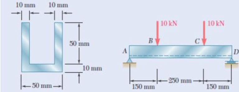
Fig. P4.11
Find the maximum tensile and compressive stresses in portion BC of the beam.
Answer to Problem 11P
The maximum compressive and tensile stress in the in the section BC are
Explanation of Solution
Given information:
Calculation:
Show the cross-section of the beam as shown in figure 1.
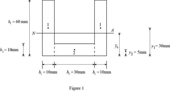
Refer to Figure 1.
Calculate the value of
Substitute
Calculate the moment of inertia
Substitute
The moment of inertia of rectangle 2 is same as the moment of inertia of rectangle 1. Then,
Calculate the moment of inertia
Substitute
Calculate the total moment of inertia (I) of the cross-section as follows:
Substitute
Refer Figure 1.
Consider the distance between the neutral axis and the top fiber and bottom fiber of the beam is
Calculate
Show the section of the beam left of C as shown in Figure 2.
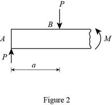
Refer to Figure 2.
Calculate the moment M using the relation:
Substitute
Calculate the value of stress
Substitute
Calculate the value of stress
Substitute
Thus, the maximum compressive and tensile stress in the in the section BC are
Want to see more full solutions like this?
Chapter 4 Solutions
Mechanics of Materials 7th Edition


- Straight rods of 0.30-in. diameter and 200-ft length are sometimes used to clear underground conduits of obstructions or to thread wires through a new conduit. The rods are made of high-strength steel and, for storage and transportation, are wrapped on spools of 5-ft diameter. Assuming that the yield strength is not exceeded, determine (a) the maximum stress in a rod, when the rod, which was initially straight, is wrapped on the spool, (b) the corresponding bending moment in the rod. Use E= 29 * 106 psi.arrow_forwardA rigid bar AB of length L = 1600 mm is hinged to a support at A and supported by two vertical wires attached at points C and D such that AC = 500mm and AD = 1200mm Both the wires have same cross sectional area of 16 mm² and made of the same material having Young's modulus of 200 GPa. The wire at C has a length of 400 mm and that at D has 800 mm. Determine the tensile stresses in the wires and downward displacement at point B of the bar when a load of 1 kN is suspended at B.arrow_forwardA 1600-lb-in. couple is applied to a wooden beam, of rectangular cross section 1.5 by 3.5 in., in a plane forming an angle of 308 with the vertical (Fig. ). Determine (a) the maximum stress in the beam and (b) the angle that the neutral surface forms with the horizontal planearrow_forward
- The member having a rectangular cross-section, Fig. a, is designed to resist a moment of 40 N # m. In order to increase its strength and rigidity, it is proposed that two small ribs be added at its bottom, Fig. b. Determine the maximum normal stress in the member for both cases.arrow_forwardAn open-link chain is obtained by bending low-carbon steel rods of 0.5-in. diameter into the shape shown (Fig. ). Knowing that the chain carries a load of 160 lb, determine (a) the largest tensile and compressive stresses in the straight portion of a link, (b) the distance between the cen-troidal and the neutral axis of a cross sectionarrow_forwardA horizontal load P of magnitude 100 kN is applied to the beam shown. Determine the largest distance a for which the maximum ten-sile stress in the beam does not exceed 75 MPaarrow_forward
- A 50-kN force is subjected to a lap joint fastened by three 20-mm diameter rivets.(a) the shearing stress in each rivet.(b) the bearing stress in each plate.(c) the maximum average tensile stress in each plate. Assume that the axial load P is distributed equally amongthe three rivets. equally among the three rivets.arrow_forwardA rod must not stretch more than 6 mm when the tension in the wire is 8 kN. Knowing that E = 105 GPa and that the maximum allowable normal stress is 150 MPa, determine the corresponding maximum length of the rod (m).arrow_forwardAn 18-m-long steel wire of 5-mm diameter is to be used in the manu-facture of a prestressed concrete beam. It is observed that the wire stretches 45 mm when a tensile force P is applied. Knowing that E5 200 GPa, determine (a) the magnitude of the force P, (b) the cor-responding normal stress in the wirearrow_forward
- Two cylindrical rods, one of steel and the other of brass, are joined at C and restrained by rigid supports at A and E. The steel rod has a length of 300 mm while the brass rod has a length of 200 mm. The diameters of the rods are shown in the figure below. A force of 60 kN is applied at point B of the steel segment. For the loading shown and knowing that modulus of elasticity values for steel and brass are respectively Es = 200 GPa and Eb = 105 GPa, determine a.) The reactions at A and E: RA and RE. b.) The deflection of point C from its original location. how to doarrow_forwardThree rods of different materials are connected and placed between rigid supports at A and D, as shown below. Properties for each of the three rods are given below. The bars are initially unstressed when the structure is assembled at 70°F. After the temperature has been increased to 250°F, determine: (a) the normal stresses in the three rods. (b) the force exerted on the rigid supports. (c) the deflections of joints B and C relative to rigid support A.arrow_forwardThe aluminum rod AD is fitted with a jacket that is used to apply a hydrostatic pressure of 6000 psi to the 12-in. portion BC of the rod. Knowing that E=10.1* 106 psi and ν=0.36, determine (a) the change in the total length AD, (b) the change in diameter at the middle of the rod, determine the forces that should be applied to the ends A and D of the rod (a) if the axial strain in portion BC of the rod is to remain zero as the hydrostatic pressure is applied, (b) if the total length AD of the rod is to remain unchangedarrow_forward
 Elements Of ElectromagneticsMechanical EngineeringISBN:9780190698614Author:Sadiku, Matthew N. O.Publisher:Oxford University Press
 Mechanics of Materials (10th Edition)Mechanical EngineeringISBN:9780134319650Author:Russell C. HibbelerPublisher:PEARSON
 Thermodynamics: An Engineering ApproachMechanical EngineeringISBN:9781259822674Author:Yunus A. Cengel Dr., Michael A. BolesPublisher:McGraw-Hill Education
 Control Systems EngineeringMechanical EngineeringISBN:9781118170519Author:Norman S. NisePublisher:WILEY
 Mechanics of Materials (MindTap Course List)Mechanical EngineeringISBN:9781337093347Author:Barry J. Goodno, James M. GerePublisher:Cengage Learning
 Engineering Mechanics: StaticsMechanical EngineeringISBN:9781118807330Author:James L. Meriam, L. G. Kraige, J. N. BoltonPublisher:WILEY