
Mechanics of Materials, Student Value Edition (10th Edition)
10th Edition
ISBN: 9780134321189
Author: Russell C. Hibbeler
Publisher: PEARSON
expand_more
expand_more
format_list_bulleted
Concept explainers
Videos
Textbook Question
Chapter 4.5, Problem 4.52P
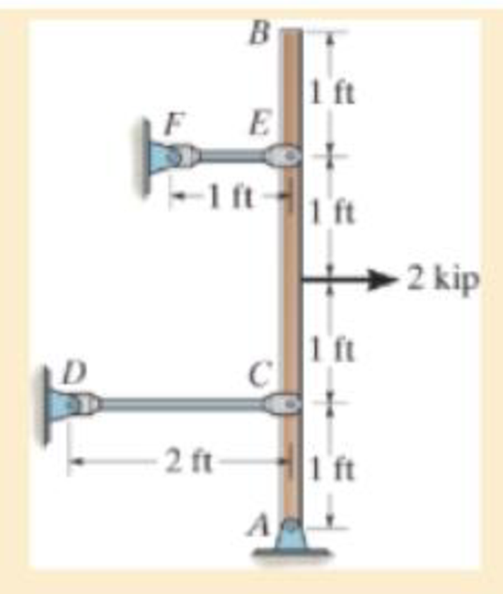
The rigid bar is pinned at A and supported by two aluminum rods, each having a diameter of 1 in. and a modulus of elasticity Eal = 10(103) ksi. If the bar is initially vertical, determine the force in each rod when the 2-kip load is applied.
Expert Solution & Answer
Want to see the full answer?
Check out a sample textbook solution
Students have asked these similar questions
The rigid bar is pinned at A and supported by two aluminum rods, each having a diameter of 1 in. and a modulus of elasticity Eal = 10(103) ksi. If the bar is initially vertical, determine the displacement of the end B when the force of 2 kip is applied.
The 304 stainless steel post A is surrounded by a red brass C83400 tube B. Both rest on the rigid surface. If a force of 25 kN is applied to the rigid cap, determine the required diameter d of the steel post so that the load is shared equally between the post and tube. The elastic modulus for brass is 101 GPa and the elastic modulus for steel is 193 GPa
The aluminum block has a rectangular cross section and is subjected to an axial compressive force of 8 kip. If the 1.5-in. side changed its length to 1.500132 in., determine the Poisson's ratio. Assume modulus of elasticity (E) = 10 x 10^3 ksi
indicate the free body diagram
Chapter 4 Solutions
Mechanics of Materials, Student Value Edition (10th Edition)
Ch. 4.2 - In each case, determine the internal normal force...Ch. 4.2 - Determine the internal normal force between...Ch. 4.2 - The post weighs 8kN/m. Determine the internal...Ch. 4.2 - The rod is subjected to an external axial force of...Ch. 4.2 - The rigid beam supports the load of 60 kN....Ch. 4.2 - The 20-mm-diameter A-36 steel rod is subjected to...Ch. 4.2 - Segments AB and CD of the assembly are solid...Ch. 4.2 - The 30-mm-diameter A992 steel rod is subjected to...Ch. 4.2 - If the 20-mm-diameter rod is made of A-36 steel...Ch. 4.2 - The 20-mm-diameter 2014-T6 aluminum rod is...
Ch. 4.2 - The 20-mm-diameter 2014-T6 aluminum rod is...Ch. 4.2 - The A992 steel rod is subjected to the loading...Ch. 4.2 - The copper shaft is subjected to the axial loads...Ch. 4.2 - The composite shaft, consisting of aluminum,...Ch. 4.2 - The composite shaft, consisting of aluminum,...Ch. 4.2 - The 2014-T6 aluminium rod has a diameter of 30 mm...Ch. 4.2 - The A-36 steel drill shaft of an oil well extends...Ch. 4.2 - The truss is made of three A-36 steel members,...Ch. 4.2 - The truss is made of three A-36 steel members,...Ch. 4.2 - The assembly consists of two 10-mm diameter red...Ch. 4.2 - The assembly consists of two 10-mm diameter red...Ch. 4.2 - The load is supported by the four 304 stainless...Ch. 4.2 - The load is supported by the four 304 stainless...Ch. 4.2 - The rigid bar is supported by the pin-connected...Ch. 4.2 - The post is made of Douglas fir and has a diameter...Ch. 4.2 - The post is made of Douglas fir and has a diameter...Ch. 4.2 - The coupling rod is subjected to a force of 5 kip....Ch. 4.2 - The pipe is stuck in the ground so that when it is...Ch. 4.2 - The is made of three pin-connected A992 steel...Ch. 4.2 - The linkage is made of three pin connected A992...Ch. 4.2 - The assembly consists of three titanium...Ch. 4.2 - The rigid beam is supported at its ends by two...Ch. 4.2 - The rigid beam is supported at its ends by two...Ch. 4.2 - The steel bar has the original dimensions shown in...Ch. 4.2 - Determine the relative displacement of one end of...Ch. 4.2 - The assembly consists of two rigid bars that are...Ch. 4.2 - The truss consists of three members, each made...Ch. 4.2 - Solve Prob. 426 when the load P acts vertically...Ch. 4.2 - The observation cage C has a weight of 250 kip and...Ch. 4.2 - The steel bar has the original dimensions shown in...Ch. 4.2 - The ball is truncated at its ends and is used to...Ch. 4.5 - The column is constructed from high-strength...Ch. 4.5 - The column is constructed from high-strength...Ch. 4.5 - The A-36 steel pipe has a 6061-T6 aluminum core....Ch. 4.5 - If column AB is made from high strength precast...Ch. 4.5 - If column AB is made from high strength precast...Ch. 4.5 - Determine the support reactions at the rigid...Ch. 4.5 - If the supports at A and C are flexible and have a...Ch. 4.5 - The load of 2000 lb is to be supported by the two...Ch. 4.5 - The load of 2000 lb is to be supported by the two...Ch. 4.5 - The A-36 steel pipe has an outer radius of 20 mm...Ch. 4.5 - The 10-mm-diameter steel bolt is surrounded by a...Ch. 4.5 - The 10-mm-diameter steel bolt is surrounded by a...Ch. 4.5 - The assembly consists of two red brass C83400...Ch. 4.5 - The rigid beam is supported by the three suspender...Ch. 4.5 - The bolt AB has a diameter of 20 mm and passes...Ch. 4.5 - If the gap between C and the rigid wall at D is...Ch. 4.5 - The support consists of a solid red brass C83400...Ch. 4.5 - If there are n fibers, each having a...Ch. 4.5 - The rigid bar is pinned at A and supported by two...Ch. 4.5 - The rigid bar is pinned at A and supported by two...Ch. 4.5 - The rigid bar is pinned at A and supported by two...Ch. 4.5 - The rigid bar is pinned at A and supported by two...Ch. 4.5 - The 2014-T6 aluminum rod AC is reinforced with the...Ch. 4.5 - The 2014-T6 aluminum rod AC is reinforced with the...Ch. 4.5 - The three suspender bars are made of A992 steel...Ch. 4.5 - The three A-36 steel wires each have a diameter of...Ch. 4.5 - The A-36 steel wires AB and AD each have a...Ch. 4.5 - The post is made from 6061-T6 aluminum and has a...Ch. 4.5 - The post is made from 6061-T6 aluminum and has a...Ch. 4.5 - The bracket is held to the wall using three A-36...Ch. 4.5 - The bracket is held to the wall using three A-36...Ch. 4.5 - If each of the posts has an unloaded length of 1 m...Ch. 4.5 - The rigid bar is supported by the two short white...Ch. 4.5 - The assembly consists of two posts AB and CD each...Ch. 4.5 - The assembly consists of two posts AB and CD each...Ch. 4.5 - The assembly consists of two posts AB and CD each...Ch. 4.5 - The wheel is subjected to a force of 18 kN from...Ch. 4.6 - The C83400-red-brass rod AB and 2014-T6- aluminum...Ch. 4.6 - The assembly has the diameters and material...Ch. 4.6 - The rod is made of A992 steel and has a diameter...Ch. 4.6 - The two cylindrical rod segments are fixed to the...Ch. 4.6 - The two cylindrical rod segments are fixed to the...Ch. 4.6 - The pipe is made of A992 steel and is connected to...Ch. 4.6 - The bronze C86100 pipe has an inner radius of 0.5...Ch. 4.6 - The 40-ft-long A-36 steel rails on a train track...Ch. 4.6 - The device is used to measure a change in...Ch. 4.6 - The bar has a cross-sectional area A, length L,...Ch. 4.6 - When the temperature is at 30C, the A-36 steel...Ch. 4.6 - When the temperature is at 30C, the A-36 steel...Ch. 4.6 - When the temperature is at 30C, the A-36 steel...Ch. 4.6 - The 50-mm-diameter cylinder is made from Am...Ch. 4.6 - The 50-mm-diameter cylinder is made from Am...Ch. 4.6 - The wires AB and AC are made of steel, and wire AD...Ch. 4.6 - The cylinder CD of the assembly is heated from T1...Ch. 4.6 - The cylinder CD of the assembly is heated from T1=...Ch. 4.6 - The metal strap has a thickness t and width w and...Ch. 4.9 - Determine the maximum normal stress developed in...Ch. 4.9 - If the allowable normal stress for the bar is...Ch. 4.9 - The steel bar has the dimensions shown. Determine...Ch. 4.9 - The A-36 steel plate has a thickness of 12 mm. If...Ch. 4.9 - Determine the maximum axial force P that can be...Ch. 4.9 - Determine the maximum normal stress developed in...Ch. 4.9 - The member is to be made from a steel plate that...Ch. 4.9 - The resulting stress distribution along section AB...Ch. 4.9 - The resulting stress distribution along section AB...Ch. 4.9 - Prob. 4.96PCh. 4.9 - The weight is suspended from steel and aluminum...Ch. 4.9 - The bar has a cross-sectional area of 0.5 in2 and...Ch. 4.9 - The distributed loading is applied to the rigid...Ch. 4.9 - The distributed loading is applied to the rigid...Ch. 4.9 - The rigid lever arm is supported by two A-36 steel...Ch. 4.9 - The rigid lever arm is supported by two A-36 steel...Ch. 4.9 - The 300-kip weight is slowly set on the top of a...Ch. 4.9 - The rigid beam is supported by three 25-mm...Ch. 4.9 - The rigid beam is supported by three 25-mm...Ch. 4.9 - The rigid beam is supported by the three posts A,...Ch. 4.9 - The rigid beam is supported by the three posts A,...Ch. 4.9 - The bar having a diameter of 2 in. is fixed...Ch. 4.9 - Determine the elongation of the bar in Prob.4108...Ch. 4.9 - The rigid beam is supported by three A-36 steel...Ch. 4 - The assembly consists of two A992 steel bolts AB...Ch. 4 - The assembly shown consists of two A992 steel...Ch. 4 - The rods each have the same 25-mm diameter and...Ch. 4 - Two A992 steel pipes, each having a...Ch. 4 - The force P is applied to the bar, which is made...Ch. 4 - The 2014-T6 aluminum rod has a diameter of 0.5 in....Ch. 4 - The 2014-T6 aluminum rod has a diameter of 0.5 in....Ch. 4 - The rigid link is supported by a pin at A and two...Ch. 4 - The joint is made from three A992 steel plates...
Knowledge Booster


Learn more about
Need a deep-dive on the concept behind this application? Look no further. Learn more about this topic, mechanical-engineering and related others by exploring similar questions and additional content below.Similar questions
- A 20-ft-long column is made of aluminum alloy 2014-T6. If it is pinned at its top and bottom, and a compressive load P is applied at point A, determine the maximum allowable magnitude of P using the equations of Sec. 13.6 and the interaction formula with (sb)allow = 20 ksi.arrow_forwardThe post is made from 606l-T6 aluminum and has a diameter of 50 mm. It is fixed supported at A and B, and at its center C there is a coiled spring attached to the rigid collar. If the spring is originally uncompressed, determine the compression in the spring when the load of P = 50 kN is applied to the collar.arrow_forwardThe brass rod is ixed at one end and free at the other end. If the length of the rod is L = 2 m, determine the greatest allowable load P that can be applied so that the rod does not buckle or yield. Also, determine the largest sidesway delection of the rod due to the loading. Ebr = 101 GPa, sY = 69 MPa.arrow_forward
- The steel pipe is fixed supported at its ends. If it is 4 m long and has an outer diameter of 50 mm, determine its required thickness so that it can support an axial load of P = 100 kN without buckling. Est = 200 GPa, sY = 250 MPa.arrow_forwardThe link AB of the pliers has the cross section dimensions 3mm x 20mm, and is made of steel with elastic modulus E= 190 GPa. Determine the value of the force F that would cause failure of the link by bucklingarrow_forwardThe truss consists of three members, each made from A-36 steel and having a cross-sectional area of 0.75 in2. Determine the greatest load P that can be applied so that the roller support at B is not displaced more than 0.03 in.arrow_forward
- The assembly consists of two rigid bars that are originally horizontal. They are supported by pins and 0.25-in.-diameter A-36 steel rods. If the vertical load of 5 kip is applied to the bottom bar AB, determine the displacement at C, B, and E.arrow_forwardThe two bars are made of a material that has the stress-strain diagram shown. If the cross-sectional area of bar AB is 1.5 in2 and BC is 4 in2, determine the largest force P that can be supported before any member fractures. Assume that buckling does not occur.arrow_forwardA rectangular wooden column has the cross section shown. If a = 3 in. and the column is subjected to an axial force of P = 15 kip, determine the maximum length the column can have to safely support the load. The column is pinned at its top and ixed at its base.arrow_forward
- The beam is supported by the three pin-connected suspender bars, each having a diameter of 0.5 in. and made from A-36 steel. Determine the greatest uniform load w that can be applied to the beam without causing AB or CB to buckle.arrow_forwardThe rigid bar is pinned at A and supported by two aluminum rods, each having a diameter of 1 in. a modulus of elasticity Eal = 10(103) ksi, and yield stress of (sY)al = 40 ksi. If the bar is initially vertical, determine the angle of tilt of the bar when the 20-kip load is applied.arrow_forwardThe stress–strain diagram of the material can be approximated by the two line segments. If a bar having a diameter of 80 mm and a length of 1.5 m is made from this material, determine the critical load provided the ends arepinned. Assume that the load acts through the axis of the bar. Use Engesser’s equation.arrow_forward
arrow_back_ios
SEE MORE QUESTIONS
arrow_forward_ios
Recommended textbooks for you
 Elements Of ElectromagneticsMechanical EngineeringISBN:9780190698614Author:Sadiku, Matthew N. O.Publisher:Oxford University Press
 Mechanics of Materials (10th Edition)Mechanical EngineeringISBN:9780134319650Author:Russell C. HibbelerPublisher:PEARSON
 Thermodynamics: An Engineering ApproachMechanical EngineeringISBN:9781259822674Author:Yunus A. Cengel Dr., Michael A. BolesPublisher:McGraw-Hill Education
 Control Systems EngineeringMechanical EngineeringISBN:9781118170519Author:Norman S. NisePublisher:WILEY
 Mechanics of Materials (MindTap Course List)Mechanical EngineeringISBN:9781337093347Author:Barry J. Goodno, James M. GerePublisher:Cengage Learning
 Engineering Mechanics: StaticsMechanical EngineeringISBN:9781118807330Author:James L. Meriam, L. G. Kraige, J. N. BoltonPublisher:WILEY
Elements Of Electromagnetics
Mechanical Engineering
ISBN:9780190698614
Author:Sadiku, Matthew N. O.
Publisher:Oxford University Press
Mechanics of Materials (10th Edition)
Mechanical Engineering
ISBN:9780134319650
Author:Russell C. Hibbeler
Publisher:PEARSON
Thermodynamics: An Engineering Approach
Mechanical Engineering
ISBN:9781259822674
Author:Yunus A. Cengel Dr., Michael A. Boles
Publisher:McGraw-Hill Education
Control Systems Engineering
Mechanical Engineering
ISBN:9781118170519
Author:Norman S. Nise
Publisher:WILEY
Mechanics of Materials (MindTap Course List)
Mechanical Engineering
ISBN:9781337093347
Author:Barry J. Goodno, James M. Gere
Publisher:Cengage Learning
Engineering Mechanics: Statics
Mechanical Engineering
ISBN:9781118807330
Author:James L. Meriam, L. G. Kraige, J. N. Bolton
Publisher:WILEY
EVERYTHING on Axial Loading Normal Stress in 10 MINUTES - Mechanics of Materials; Author: Less Boring Lectures;https://www.youtube.com/watch?v=jQ-fNqZWrNg;License: Standard YouTube License, CC-BY