
Mechanics of Materials, Student Value Edition (10th Edition)
10th Edition
ISBN: 9780134321189
Author: Russell C. Hibbeler
Publisher: PEARSON
expand_more
expand_more
format_list_bulleted
Concept explainers
Videos
Textbook Question
Chapter 4.6, Problem 4.83P
The wires AB and AC are made of steel, and wire AD is made of copper. Before the 150-lb force is applied, AB and AC are each 60 in. long and AD is 40 in. long. If the temperature is increased by 80°F, determine the force in each wire needed to support the load. Each wire has a cross-sectional area of 0 0123 in2. Take Est = 29(103) ksi, Ecu = 17(103) ksi, αst = 8(10-6)/°F, αcu = 9.60(10-6)/°F.
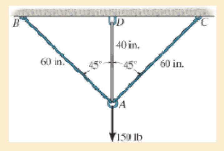
Prob. 4–83
Expert Solution & Answer

Trending nowThis is a popular solution!

Students have asked these similar questions
The wires AB and AC are made of steel, and wire AD is made of copper. Before the 150-lb force is applied, AB and AC are each 60 in. long and AD is 40 in. long. If the temperature is increased by 80
F, determine the force in each wire needed to support the load. Each wire has a cross-sectionalarea of 0.0123 in2. Take Est = 29(10 3) ksi, Ecu = 17(10 3) ksi, fast = 8(10 6)>
F, acu = 9.60(10 -6)>
F.
The load of 2000 lb is to be supported by the two vertical steel wires for which sY = 70 ksi. Originally wire AB is 60 in. long and wire AC is 60.04 in. long. Determine the force developed in each wire after the load is suspended. Each wire has a cross-sectional area of 0.02 in2. Est = 29.0(103) ksi.
The inner ring A has an inner radius r1 and outer radius r2. The outer ring B has an inner radius r3 and an outer radius r4, and r2 7 r3. If the outer ring is heated and then fitted over the inner ring, determine the pressure between the two rings when ring B reaches the temperature of the inner ring. The material has a modulus of elasticity of E and a coefficient of thermal expansion of a.
Chapter 4 Solutions
Mechanics of Materials, Student Value Edition (10th Edition)
Ch. 4.2 - In each case, determine the internal normal force...Ch. 4.2 - Determine the internal normal force between...Ch. 4.2 - The post weighs 8kN/m. Determine the internal...Ch. 4.2 - The rod is subjected to an external axial force of...Ch. 4.2 - The rigid beam supports the load of 60 kN....Ch. 4.2 - The 20-mm-diameter A-36 steel rod is subjected to...Ch. 4.2 - Segments AB and CD of the assembly are solid...Ch. 4.2 - The 30-mm-diameter A992 steel rod is subjected to...Ch. 4.2 - If the 20-mm-diameter rod is made of A-36 steel...Ch. 4.2 - The 20-mm-diameter 2014-T6 aluminum rod is...
Ch. 4.2 - The 20-mm-diameter 2014-T6 aluminum rod is...Ch. 4.2 - The A992 steel rod is subjected to the loading...Ch. 4.2 - The copper shaft is subjected to the axial loads...Ch. 4.2 - The composite shaft, consisting of aluminum,...Ch. 4.2 - The composite shaft, consisting of aluminum,...Ch. 4.2 - The 2014-T6 aluminium rod has a diameter of 30 mm...Ch. 4.2 - The A-36 steel drill shaft of an oil well extends...Ch. 4.2 - The truss is made of three A-36 steel members,...Ch. 4.2 - The truss is made of three A-36 steel members,...Ch. 4.2 - The assembly consists of two 10-mm diameter red...Ch. 4.2 - The assembly consists of two 10-mm diameter red...Ch. 4.2 - The load is supported by the four 304 stainless...Ch. 4.2 - The load is supported by the four 304 stainless...Ch. 4.2 - The rigid bar is supported by the pin-connected...Ch. 4.2 - The post is made of Douglas fir and has a diameter...Ch. 4.2 - The post is made of Douglas fir and has a diameter...Ch. 4.2 - The coupling rod is subjected to a force of 5 kip....Ch. 4.2 - The pipe is stuck in the ground so that when it is...Ch. 4.2 - The is made of three pin-connected A992 steel...Ch. 4.2 - The linkage is made of three pin connected A992...Ch. 4.2 - The assembly consists of three titanium...Ch. 4.2 - The rigid beam is supported at its ends by two...Ch. 4.2 - The rigid beam is supported at its ends by two...Ch. 4.2 - The steel bar has the original dimensions shown in...Ch. 4.2 - Determine the relative displacement of one end of...Ch. 4.2 - The assembly consists of two rigid bars that are...Ch. 4.2 - The truss consists of three members, each made...Ch. 4.2 - Solve Prob. 426 when the load P acts vertically...Ch. 4.2 - The observation cage C has a weight of 250 kip and...Ch. 4.2 - The steel bar has the original dimensions shown in...Ch. 4.2 - The ball is truncated at its ends and is used to...Ch. 4.5 - The column is constructed from high-strength...Ch. 4.5 - The column is constructed from high-strength...Ch. 4.5 - The A-36 steel pipe has a 6061-T6 aluminum core....Ch. 4.5 - If column AB is made from high strength precast...Ch. 4.5 - If column AB is made from high strength precast...Ch. 4.5 - Determine the support reactions at the rigid...Ch. 4.5 - If the supports at A and C are flexible and have a...Ch. 4.5 - The load of 2000 lb is to be supported by the two...Ch. 4.5 - The load of 2000 lb is to be supported by the two...Ch. 4.5 - The A-36 steel pipe has an outer radius of 20 mm...Ch. 4.5 - The 10-mm-diameter steel bolt is surrounded by a...Ch. 4.5 - The 10-mm-diameter steel bolt is surrounded by a...Ch. 4.5 - The assembly consists of two red brass C83400...Ch. 4.5 - The rigid beam is supported by the three suspender...Ch. 4.5 - The bolt AB has a diameter of 20 mm and passes...Ch. 4.5 - If the gap between C and the rigid wall at D is...Ch. 4.5 - The support consists of a solid red brass C83400...Ch. 4.5 - If there are n fibers, each having a...Ch. 4.5 - The rigid bar is pinned at A and supported by two...Ch. 4.5 - The rigid bar is pinned at A and supported by two...Ch. 4.5 - The rigid bar is pinned at A and supported by two...Ch. 4.5 - The rigid bar is pinned at A and supported by two...Ch. 4.5 - The 2014-T6 aluminum rod AC is reinforced with the...Ch. 4.5 - The 2014-T6 aluminum rod AC is reinforced with the...Ch. 4.5 - The three suspender bars are made of A992 steel...Ch. 4.5 - The three A-36 steel wires each have a diameter of...Ch. 4.5 - The A-36 steel wires AB and AD each have a...Ch. 4.5 - The post is made from 6061-T6 aluminum and has a...Ch. 4.5 - The post is made from 6061-T6 aluminum and has a...Ch. 4.5 - The bracket is held to the wall using three A-36...Ch. 4.5 - The bracket is held to the wall using three A-36...Ch. 4.5 - If each of the posts has an unloaded length of 1 m...Ch. 4.5 - The rigid bar is supported by the two short white...Ch. 4.5 - The assembly consists of two posts AB and CD each...Ch. 4.5 - The assembly consists of two posts AB and CD each...Ch. 4.5 - The assembly consists of two posts AB and CD each...Ch. 4.5 - The wheel is subjected to a force of 18 kN from...Ch. 4.6 - The C83400-red-brass rod AB and 2014-T6- aluminum...Ch. 4.6 - The assembly has the diameters and material...Ch. 4.6 - The rod is made of A992 steel and has a diameter...Ch. 4.6 - The two cylindrical rod segments are fixed to the...Ch. 4.6 - The two cylindrical rod segments are fixed to the...Ch. 4.6 - The pipe is made of A992 steel and is connected to...Ch. 4.6 - The bronze C86100 pipe has an inner radius of 0.5...Ch. 4.6 - The 40-ft-long A-36 steel rails on a train track...Ch. 4.6 - The device is used to measure a change in...Ch. 4.6 - The bar has a cross-sectional area A, length L,...Ch. 4.6 - When the temperature is at 30C, the A-36 steel...Ch. 4.6 - When the temperature is at 30C, the A-36 steel...Ch. 4.6 - When the temperature is at 30C, the A-36 steel...Ch. 4.6 - The 50-mm-diameter cylinder is made from Am...Ch. 4.6 - The 50-mm-diameter cylinder is made from Am...Ch. 4.6 - The wires AB and AC are made of steel, and wire AD...Ch. 4.6 - The cylinder CD of the assembly is heated from T1...Ch. 4.6 - The cylinder CD of the assembly is heated from T1=...Ch. 4.6 - The metal strap has a thickness t and width w and...Ch. 4.9 - Determine the maximum normal stress developed in...Ch. 4.9 - If the allowable normal stress for the bar is...Ch. 4.9 - The steel bar has the dimensions shown. Determine...Ch. 4.9 - The A-36 steel plate has a thickness of 12 mm. If...Ch. 4.9 - Determine the maximum axial force P that can be...Ch. 4.9 - Determine the maximum normal stress developed in...Ch. 4.9 - The member is to be made from a steel plate that...Ch. 4.9 - The resulting stress distribution along section AB...Ch. 4.9 - The resulting stress distribution along section AB...Ch. 4.9 - Prob. 4.96PCh. 4.9 - The weight is suspended from steel and aluminum...Ch. 4.9 - The bar has a cross-sectional area of 0.5 in2 and...Ch. 4.9 - The distributed loading is applied to the rigid...Ch. 4.9 - The distributed loading is applied to the rigid...Ch. 4.9 - The rigid lever arm is supported by two A-36 steel...Ch. 4.9 - The rigid lever arm is supported by two A-36 steel...Ch. 4.9 - The 300-kip weight is slowly set on the top of a...Ch. 4.9 - The rigid beam is supported by three 25-mm...Ch. 4.9 - The rigid beam is supported by three 25-mm...Ch. 4.9 - The rigid beam is supported by the three posts A,...Ch. 4.9 - The rigid beam is supported by the three posts A,...Ch. 4.9 - The bar having a diameter of 2 in. is fixed...Ch. 4.9 - Determine the elongation of the bar in Prob.4108...Ch. 4.9 - The rigid beam is supported by three A-36 steel...Ch. 4 - The assembly consists of two A992 steel bolts AB...Ch. 4 - The assembly shown consists of two A992 steel...Ch. 4 - The rods each have the same 25-mm diameter and...Ch. 4 - Two A992 steel pipes, each having a...Ch. 4 - The force P is applied to the bar, which is made...Ch. 4 - The 2014-T6 aluminum rod has a diameter of 0.5 in....Ch. 4 - The 2014-T6 aluminum rod has a diameter of 0.5 in....Ch. 4 - The rigid link is supported by a pin at A and two...Ch. 4 - The joint is made from three A992 steel plates...
Knowledge Booster


Learn more about
Need a deep-dive on the concept behind this application? Look no further. Learn more about this topic, mechanical-engineering and related others by exploring similar questions and additional content below.Similar questions
- The load of 2000 lb is to be supported by the two vertical steel wires for which sY = 70 ksi. Originally wire AB is 60 in. long and wire AC is 60.04 in. long. Determine the cross-sectional area of AB if the load is to be shared equally between both wires. Wire AC has a cross-sectional area of 0.02 in2. Est = 29.0(103) ksi.arrow_forwardThe plastic 50-mm diameter rod is placed in a 51-mm-diameter hole with rigid walls. Determine the change in the length of the rod after the 8 kN load is applied. Use E = 40 MPa and v=0.45 for the rod.arrow_forwardThe 1021-kg uniform bar AB is suspended from two cables AC and BD each with cross-sectional area 472 mm2. Find the magnitude of P (in N) that can be safely applied to the bar if the stresses in AC and BD are limited to 110 MPa and 51 MPa, respectively. Express your answer in two decimal places.arrow_forward
- The acrylic plastic rod is 200 mm long and 15 mm in diameter. If an axial load of 300 N is applied to it, determine the change in its length and the change in its diameter. Ep = 2.70 GPa, np = 0.4.arrow_forwardThe three-bar truss in Fig. a is subjected to a horizontal force of 5 kip. If the cross-sectional area of each member is 0.20 in2, determine the horizontal displacement at point B. E = 29(103) ksi.arrow_forwardThe 80-kg lamp is supported by two rods AB and BC as shown in Figure. If AB has a diameter of 10 mm and BC has a diameter of 8 mm, determine the average normal stress in each rod.arrow_forward
- The force P is applied to the bar, which is made from an elastic perfectly plastic material. Construct a graph to show how the force in each section AB and BC (vertical axis) varies as P (horizontal axis) is increased. The bar has cross-sectional areas of 1 in2 in region AB and 4 in2 in region BC. Take sY = 30 ksi.arrow_forwardThe metal strap has a thickness t and width w and is subjected to a temperature gradient T1 to T2 (T1 6 T2). This causes the modulus of elasticity for the material to vary linearly from E1 at the top to a smaller amount E2 at the bottom. As a result, for any vertical position y, measured from the top surface, E = [(E2 - E1)>w]y + E1. Determine the position d where the axial force P must be applied so that the bar stretches uniformly over its cross-section. warrow_forwardThe bar has a cross-sectional area A, length L, modulus of elasticity E, and coefficient of thermal expansion a. The temperature of the bar changes uniformly along its length from TA at A to TB at B so that at any point x alongthe bar T = TA + x(TB - TA)>L. Determine the force the bar exerts on the rigid walls. Initially, no axial force is in the bar and the bar has a temperature of TA.arrow_forward
- A cylindrical pressure vessel has an inner diameter of 4 ft and a thicknessof 1 2 in. Determine the maximum internal pressure it can sustain so that neither its circumferential nor its longitudinal stress component exceeds 20 ksi. Under the same conditions, what is the maximum internal pressure that a similar-size spherical vessel can sustain?arrow_forwardThe cylindrical bar composed of two parts (AB and BC) is fixed at ends A and C. The two parts are made of different materials with different cross-sections. An external load ? =28 kN is applied at point B. The cross-sectional area of AB and BC part is 0.9 cm2and 0.3 cm2, respectively. The modulus of elasticity of the AB and BC part is 40 GPa and 200 GPa, respectively. Determine the force reactions at ends A and C.arrow_forwardThe ring, with dimensions shown, is placed over a flexible membrane which is pumped up with a pressure p. The thickness r,-r; is small compared to r; (a) Determine the axial force F in the ring in terms of p, w and r;. Hint: Consider a FBD by cutting the ring+membrane in two. (b) Determine the hoop stress in the ring. (c) Determine the hoop strain in the ring. The modulus of elasticity for the ring is E. (d) Relate the hoop strain to the change in the inner radius of the ring after this pressure is applied, and use this to get the change in the inner radius in terms of p, E, w, r, and ri- (PLEASE ANSWER ASAP AND CORRECTLY)!arrow_forward
arrow_back_ios
SEE MORE QUESTIONS
arrow_forward_ios
Recommended textbooks for you
 Elements Of ElectromagneticsMechanical EngineeringISBN:9780190698614Author:Sadiku, Matthew N. O.Publisher:Oxford University Press
 Mechanics of Materials (10th Edition)Mechanical EngineeringISBN:9780134319650Author:Russell C. HibbelerPublisher:PEARSON
 Thermodynamics: An Engineering ApproachMechanical EngineeringISBN:9781259822674Author:Yunus A. Cengel Dr., Michael A. BolesPublisher:McGraw-Hill Education
 Control Systems EngineeringMechanical EngineeringISBN:9781118170519Author:Norman S. NisePublisher:WILEY
 Mechanics of Materials (MindTap Course List)Mechanical EngineeringISBN:9781337093347Author:Barry J. Goodno, James M. GerePublisher:Cengage Learning
 Engineering Mechanics: StaticsMechanical EngineeringISBN:9781118807330Author:James L. Meriam, L. G. Kraige, J. N. BoltonPublisher:WILEY
Elements Of Electromagnetics
Mechanical Engineering
ISBN:9780190698614
Author:Sadiku, Matthew N. O.
Publisher:Oxford University Press
Mechanics of Materials (10th Edition)
Mechanical Engineering
ISBN:9780134319650
Author:Russell C. Hibbeler
Publisher:PEARSON
Thermodynamics: An Engineering Approach
Mechanical Engineering
ISBN:9781259822674
Author:Yunus A. Cengel Dr., Michael A. Boles
Publisher:McGraw-Hill Education
Control Systems Engineering
Mechanical Engineering
ISBN:9781118170519
Author:Norman S. Nise
Publisher:WILEY
Mechanics of Materials (MindTap Course List)
Mechanical Engineering
ISBN:9781337093347
Author:Barry J. Goodno, James M. Gere
Publisher:Cengage Learning
Engineering Mechanics: Statics
Mechanical Engineering
ISBN:9781118807330
Author:James L. Meriam, L. G. Kraige, J. N. Bolton
Publisher:WILEY
Understanding Conduction and the Heat Equation; Author: The Efficient Engineer;https://www.youtube.com/watch?v=6jQsLAqrZGQ;License: Standard youtube license