
STANDALONE CODE MECHANICS OF MATERIALS-M
11th Edition
ISBN: 9780137605200
Author: HIBBELER
Publisher: PEARSON
expand_more
expand_more
format_list_bulleted
Concept explainers
Videos
Textbook Question
Chapter 4.5, Problem 57P
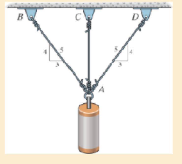
The A-36 steel wires AB and AD each have a diameter of 2 mm and unloaded lengths of each wire are LAC = 1.60 m and LAB = LAD = 2.00 m. Determine the required diameter of wire AC so that each wire is subjected to the same force when the 150-kg mass is suspended from the ring at A.
Expert Solution & Answer
Want to see the full answer?
Check out a sample textbook solution
Students have asked these similar questions
The A-36 steel wires AB and AD each have a diameter of 2 mm and the unloaded lengths of each wire are LAC = 1.60 m and LAB = LAD = 2.00 m. Determine the required diameter of wire AC so that each wire is subjectedto the same force when the 150-kg mass is suspended from the ring at A.
Determine the magnitude of the pin force at A.
Assume W = 830 lb, a = 5.5 ft, b = 4.0 ft, r = 8 in.
r
W
с
Answer: A = i
a
B
a
A
D
lb
b
The oven door is spring loaded at C and pinned at A. Determine the magnitude of the normal force at section a-a that lies just to the right of C if W = 24.6 lb and 0 =
32°.
B
8 in.
O 20.9 lb
O 21.7 lb
O 18.6 lb
O 19.3 lb
O 22.4 lb
10 in.-
5 in.
12 in.
Chapter 4 Solutions
STANDALONE CODE MECHANICS OF MATERIALS-M
Ch. 4.2 - The 20-mm-diameter A-36 steel rod is subjected to...Ch. 4.2 - Segments AB and CD of the assembly are solid...Ch. 4.2 - The 30-mm-diameter A992 steel rod is subjected to...Ch. 4.2 - If the 20-mm-diameter rod is made of A-36 steel...Ch. 4.2 - The 20-mm-diameter 2014-T6 aluminum rod is...Ch. 4.2 - The 20-mm-diameter 2014-T6 aluminum rod is...Ch. 4.2 - The copper shaft is subjected to the axial loads...Ch. 4.2 - The A-36 steel rod is subjected to the loading...Ch. 4.2 - The A-36 steel rod is subjected to the loading...Ch. 4.2 - The A-36 steel drill shaft of an oil well extends...
Ch. 4.2 - Prob. 8PCh. 4.2 - The post is made of Douglas fir and has a diameter...Ch. 4.2 - The post is made of Douglas fir and has a diameter...Ch. 4.2 - The coupling rod is subjected to a force of 5 kip....Ch. 4.2 - The pipe is stuck in the ground so that when it is...Ch. 4.2 - The assembly consists of three titanium...Ch. 4.2 - The assembly consists of two rigid bars that are...Ch. 4.2 - The truss consists of three members, each made...Ch. 4.2 - Solve Prob. 426 when the load P acts vertically...Ch. 4.2 - The ball is truncated at its ends and is used to...Ch. 4.5 - The column is constructed from high-strength...Ch. 4.5 - The column is constructed from high-strength...Ch. 4.5 - The A-36 steel pipe has a 6061-T6 aluminum core....Ch. 4.5 - The 304 stainless steel post A has a diameter of...Ch. 4.5 - The 304 stainless steel post A is surrounded by a...Ch. 4.5 - The 10-mm-diameter steel bolt is surrounded by a...Ch. 4.5 - The rigid beam is supported by the three suspender...Ch. 4.5 - The bolt AB has a diameter of 20 mm and passes...Ch. 4.5 - If the gap between C and the rigid wall at D is...Ch. 4.5 - The support consists of a solid red brass C83400...Ch. 4.5 - Prob. 55PCh. 4.5 - The three A-36 steel wires each have a diameter of...Ch. 4.5 - The A-36 steel wires AB and AD each have a...Ch. 4.5 - The assembly consists of two posts AB and CD each...Ch. 4.5 - The assembly consists of two posts AB and CD each...Ch. 4.5 - The assembly consists of two posts AB and CD each...Ch. 4.5 - The wheel is subjected to a force of 18 kN from...Ch. 4.6 - The C83400-red-brass rod AB and 2014-T6- aluminum...Ch. 4.6 - The assembly has the diameters and material...Ch. 4.6 - Prob. 72PCh. 4.6 - Prob. 77PCh. 4.6 - Prob. 80PCh. 4.6 - The 50-mm-diameter cylinder is made from Am...Ch. 4.6 - The 50-mm-diameter cylinder is made from Am...Ch. 4.6 - The metal strap has a thickness t and width w and...Ch. 4.9 - Determine the maximum normal stress developed in...Ch. 4.9 - If the allowable normal stress for the bar is...Ch. 4.9 - Prob. 89PCh. 4.9 - The A-36 steel plate has a thickness of 12 mm. If...Ch. 4.9 - Determine the maximum axial force P that can be...Ch. 4.9 - Determine the maximum normal stress developed in...Ch. 4.9 - The member is to be made from a steel plate that...Ch. 4.9 - Prob. 96PCh. 4.9 - The bar has a cross-sectional area of 0.5 in2 and...Ch. 4.9 - The distributed loading is applied to the rigid...Ch. 4.9 - The distributed loading is applied to the rigid...Ch. 4.9 - The rigid lever arm is supported by two A-36 steel...Ch. 4.9 - The rigid lever arm is supported by two A-36 steel...Ch. 4.9 - The wire BC has a diameter of 0.125 in. and the...Ch. 4.9 - Prob. 104PCh. 4.9 - Prob. 106PCh. 4 - The assembly consists of two A992 steel bolts AB...Ch. 4 - The assembly shown consists of two A992 steel...Ch. 4 - The rods each have the same 25-mm diameter and...Ch. 4 - Two A992 steel pipes, each having a...Ch. 4 - The force P is applied to the bar, which is made...Ch. 4 - The 2014-T6 aluminum rod has a diameter of 0.5 in....Ch. 4 - The 2014-T6 aluminum rod has a diameter of 0.5 in....Ch. 4 - The rigid link is supported by a pin at A and two...Ch. 4 - The joint is made from three A992 steel plates...
Knowledge Booster


Learn more about
Need a deep-dive on the concept behind this application? Look no further. Learn more about this topic, mechanical-engineering and related others by exploring similar questions and additional content below.Similar questions
- The bracket is held to the wall using three A-36 steel bolts at B, C, and D. Each bolt has a diameter of 0.5 in. and an unstretched length of 2 in. If a force of 800 lb is placed on the bracket as shown, determine how far, s, the top bracket at bolt D moves away from the wall. For the calculation, assume that the bolts carry no shear; rather, the vertical force of 800 lb is supported by the toe at A. Also, assume that the wall and bracket are rigid. A greatly exaggerated deformation of the bolts is shown.arrow_forwardDetermine the magnitude of the pin force at A. Assume W = 750 lb, a = 2.7 ft, b = 2.0 ft, r = 6 in. a a r B A C W Answer: A = i D lb barrow_forwardThe baloon is in balance with 3 ropes. If each of the rope can stand to 500N tensile force, find the minimum F force that the ropes will not broke.arrow_forward
- The structure is comprised of rigid bars AB and BCD supported by hinges at A and D. A steel rod at C provides additional support to the system. As shown, there is a roller connection between the bars at B. Determine the magnitude of the force P applied as shown if the vertical displacement of point B is limited to 1.5 mm. Neglect the weights of the bars.arrow_forward2-19. The load P applied to the pin-con- nected frame shown stretches cable CD 2.5 mm. The area of the cable is 150 mm2 and E = 210 000 MN/m2. Determine P. Ans: 39.4 kN. E 3 m C D 3 m 2 m 2 marrow_forward3/15 Three cables are joined at the junction ring C. Deter- mine the tensions in cables AC and BC caused by the weight of the 30-kgkylinder. 45 15° 30 30 kg cylinderarrow_forward
- P1-1. Draw a free-body diagram of the ring at A and identify each force. 30 45 200 N 500 Narrow_forwardThe ABD bracket is supported by a pin at A and the cable DE. Determine the internal forces immediately to the left of the load.Template: (On CD) F= 270 N; M=43.2 N.m; V = 90 Narrow_forwardNeed a answer to 3 decimal pointsarrow_forward
- The structure is comprised of rigid bars AB and BCD supported by hinges at A and D. A steel rod at C provides additional support to the system. As shown, there is a roller connection between the bars at B. Determine the magnitude of the force P applied as shown if the vertical displacement of point B is limited to 1.5 mm. Neglect the weights of the bars. ( E = 200 GPa A = 300 mm2 L= 3 m A 2 m 2 m C D 1.5 m 3.0 marrow_forwardDetermine the magnitude of the horizontal force F and the support reactions at pin A.If the cord CB can sustain a maximum load of 1500N.arrow_forwardThe pumping unit is used to recover oil When the walking beam ABC is horizontal, the force acting in the wireline at the well head is Fe 250 Ib. Determine the torque M which must be exerted by the motor in order to evercome this load. The horse-head Cweighs 59 lb and has a center of gravity at Ge. The walking beam ABC has a weight of 130 Ib and a center of gravity at Gn and the counterweight has a weight of 210 Ib and a center of gravity at Gw. The pitman, AD is pin connected at its ends and has negligible weight (Eguee 1) E Redew Part A Detemine the torque M which must be exerted by the motor Express your answer to three significant figures and include the appropriate units. Figure 1 of 1 Value lb ft 68 16 Submit Previoun Answecs HenuestAnswet X Incorrect: Try Again 250 < Return to Assignment Provide Eeedbackarrow_forward
arrow_back_ios
SEE MORE QUESTIONS
arrow_forward_ios
Recommended textbooks for you
 Elements Of ElectromagneticsMechanical EngineeringISBN:9780190698614Author:Sadiku, Matthew N. O.Publisher:Oxford University Press
 Mechanics of Materials (10th Edition)Mechanical EngineeringISBN:9780134319650Author:Russell C. HibbelerPublisher:PEARSON
 Thermodynamics: An Engineering ApproachMechanical EngineeringISBN:9781259822674Author:Yunus A. Cengel Dr., Michael A. BolesPublisher:McGraw-Hill Education
 Control Systems EngineeringMechanical EngineeringISBN:9781118170519Author:Norman S. NisePublisher:WILEY
 Mechanics of Materials (MindTap Course List)Mechanical EngineeringISBN:9781337093347Author:Barry J. Goodno, James M. GerePublisher:Cengage Learning
 Engineering Mechanics: StaticsMechanical EngineeringISBN:9781118807330Author:James L. Meriam, L. G. Kraige, J. N. BoltonPublisher:WILEY
Elements Of Electromagnetics
Mechanical Engineering
ISBN:9780190698614
Author:Sadiku, Matthew N. O.
Publisher:Oxford University Press
Mechanics of Materials (10th Edition)
Mechanical Engineering
ISBN:9780134319650
Author:Russell C. Hibbeler
Publisher:PEARSON
Thermodynamics: An Engineering Approach
Mechanical Engineering
ISBN:9781259822674
Author:Yunus A. Cengel Dr., Michael A. Boles
Publisher:McGraw-Hill Education
Control Systems Engineering
Mechanical Engineering
ISBN:9781118170519
Author:Norman S. Nise
Publisher:WILEY
Mechanics of Materials (MindTap Course List)
Mechanical Engineering
ISBN:9781337093347
Author:Barry J. Goodno, James M. Gere
Publisher:Cengage Learning
Engineering Mechanics: Statics
Mechanical Engineering
ISBN:9781118807330
Author:James L. Meriam, L. G. Kraige, J. N. Bolton
Publisher:WILEY
EVERYTHING on Axial Loading Normal Stress in 10 MINUTES - Mechanics of Materials; Author: Less Boring Lectures;https://www.youtube.com/watch?v=jQ-fNqZWrNg;License: Standard YouTube License, CC-BY