
STANDALONE CODE MECHANICS OF MATERIALS-M
11th Edition
ISBN: 9780137605200
Author: HIBBELER
Publisher: PEARSON
expand_more
expand_more
format_list_bulleted
Concept explainers
Videos
Textbook Question
Chapter 4.9, Problem 102P
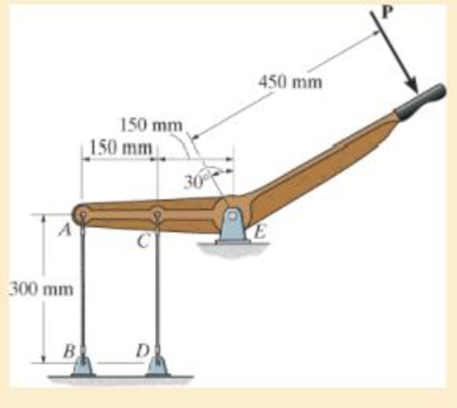
The rigid lever arm is supported by two A-36 steel wires having the same diameter of 4 mm. Determine the smallest force P that will cause (a) only one of the wires to yield; (b) both wires to yield. Consider A-36 steel as an elastic perfectly plastic material.
Prob. 4–102
Expert Solution & Answer
Want to see the full answer?
Check out a sample textbook solution
Students have asked these similar questions
4.
The rigid lever arm is supported by two A-36 steel
wires having the same diameter of 4 mm. If a force of
P = 3 kN is applied to the handle, determine the force
developed in both wires and their corresponding elongations.
Consider A-36 steel as an elastic-perfectly plastic material.
450 mm
150 mm
150 mm
30
300 mm
B.
The rigid lever arm is supported by two A-36 steel wires having the same diameter of 4 mm. If a force of P = 3 kN is applied to the handle, determine the force developed in both wires and their corresponding elongations. Consider A-36 steel as an elastic perfectly plastic material.
The rigid lever arm is supported by two A-36 steel wires having the same diameter of 4 mm. Determine the smallest force P that will cause (a) only one of the wires to yield; (b) both wires to yield. Consider A-36 steel as anelastic perfectly plastic material.
Chapter 4 Solutions
STANDALONE CODE MECHANICS OF MATERIALS-M
Ch. 4.2 - The 20-mm-diameter A-36 steel rod is subjected to...Ch. 4.2 - Segments AB and CD of the assembly are solid...Ch. 4.2 - The 30-mm-diameter A992 steel rod is subjected to...Ch. 4.2 - If the 20-mm-diameter rod is made of A-36 steel...Ch. 4.2 - The 20-mm-diameter 2014-T6 aluminum rod is...Ch. 4.2 - The 20-mm-diameter 2014-T6 aluminum rod is...Ch. 4.2 - The copper shaft is subjected to the axial loads...Ch. 4.2 - The A-36 steel rod is subjected to the loading...Ch. 4.2 - The A-36 steel rod is subjected to the loading...Ch. 4.2 - The A-36 steel drill shaft of an oil well extends...
Ch. 4.2 - Prob. 8PCh. 4.2 - The post is made of Douglas fir and has a diameter...Ch. 4.2 - The post is made of Douglas fir and has a diameter...Ch. 4.2 - The coupling rod is subjected to a force of 5 kip....Ch. 4.2 - The pipe is stuck in the ground so that when it is...Ch. 4.2 - The assembly consists of three titanium...Ch. 4.2 - The assembly consists of two rigid bars that are...Ch. 4.2 - The truss consists of three members, each made...Ch. 4.2 - Solve Prob. 426 when the load P acts vertically...Ch. 4.2 - The ball is truncated at its ends and is used to...Ch. 4.5 - The column is constructed from high-strength...Ch. 4.5 - The column is constructed from high-strength...Ch. 4.5 - The A-36 steel pipe has a 6061-T6 aluminum core....Ch. 4.5 - The 304 stainless steel post A has a diameter of...Ch. 4.5 - The 304 stainless steel post A is surrounded by a...Ch. 4.5 - The 10-mm-diameter steel bolt is surrounded by a...Ch. 4.5 - The rigid beam is supported by the three suspender...Ch. 4.5 - The bolt AB has a diameter of 20 mm and passes...Ch. 4.5 - If the gap between C and the rigid wall at D is...Ch. 4.5 - The support consists of a solid red brass C83400...Ch. 4.5 - Prob. 55PCh. 4.5 - The three A-36 steel wires each have a diameter of...Ch. 4.5 - The A-36 steel wires AB and AD each have a...Ch. 4.5 - The assembly consists of two posts AB and CD each...Ch. 4.5 - The assembly consists of two posts AB and CD each...Ch. 4.5 - The assembly consists of two posts AB and CD each...Ch. 4.5 - The wheel is subjected to a force of 18 kN from...Ch. 4.6 - The C83400-red-brass rod AB and 2014-T6- aluminum...Ch. 4.6 - The assembly has the diameters and material...Ch. 4.6 - Prob. 72PCh. 4.6 - Prob. 77PCh. 4.6 - Prob. 80PCh. 4.6 - The 50-mm-diameter cylinder is made from Am...Ch. 4.6 - The 50-mm-diameter cylinder is made from Am...Ch. 4.6 - The metal strap has a thickness t and width w and...Ch. 4.9 - Determine the maximum normal stress developed in...Ch. 4.9 - If the allowable normal stress for the bar is...Ch. 4.9 - Prob. 89PCh. 4.9 - The A-36 steel plate has a thickness of 12 mm. If...Ch. 4.9 - Determine the maximum axial force P that can be...Ch. 4.9 - Determine the maximum normal stress developed in...Ch. 4.9 - The member is to be made from a steel plate that...Ch. 4.9 - Prob. 96PCh. 4.9 - The bar has a cross-sectional area of 0.5 in2 and...Ch. 4.9 - The distributed loading is applied to the rigid...Ch. 4.9 - The distributed loading is applied to the rigid...Ch. 4.9 - The rigid lever arm is supported by two A-36 steel...Ch. 4.9 - The rigid lever arm is supported by two A-36 steel...Ch. 4.9 - The wire BC has a diameter of 0.125 in. and the...Ch. 4.9 - Prob. 104PCh. 4.9 - Prob. 106PCh. 4 - The assembly consists of two A992 steel bolts AB...Ch. 4 - The assembly shown consists of two A992 steel...Ch. 4 - The rods each have the same 25-mm diameter and...Ch. 4 - Two A992 steel pipes, each having a...Ch. 4 - The force P is applied to the bar, which is made...Ch. 4 - The 2014-T6 aluminum rod has a diameter of 0.5 in....Ch. 4 - The 2014-T6 aluminum rod has a diameter of 0.5 in....Ch. 4 - The rigid link is supported by a pin at A and two...Ch. 4 - The joint is made from three A992 steel plates...
Knowledge Booster


Learn more about
Need a deep-dive on the concept behind this application? Look no further. Learn more about this topic, mechanical-engineering and related others by exploring similar questions and additional content below.Similar questions
- The rigid beam is supported by three 25-mm diameter A-36 steel rods. If the beam supports the force of P=230 kN, determine the force developed in each rod. Consider the steel to be an elastic perfectly plastic material. Detailed solutionarrow_forward3-31. The shear stress-strain diagram for a steel alloy is shown in the figure. If a bolt having a diameter of 0.75 in. is made of this material and used in the double lap joint, determine the modulus of elasticity E and the force P required to cause the material to yield. Take v = 0.3. P= 7(ksi) 60 0.00545 Prob. 3-31 P/2 P/2 y(rad)arrow_forwardFind the reaction at A due to the uniform loading and the applied couple. The force reaction is positive if upward, negative if downward. The moment reaction is positive if counterclockwise, negative if clockwise. 2.5 kN/m 11.1 kN-m A 2.0 m 2.0 m Answers: RA = i kN MA = i kN-marrow_forward
- 3–26. The thin-walled tube is subjected to an axial force of 40 kN. If the tube elongates 3 mm and its circumference decreases 0.09 mm, determine the modulus of elasticity, Poisson's ratio, and the shear modulus of the tube's material. The material behaves elastically. 40 kN 900 mm | 10 mm 40 kN 12.5 mmarrow_forwardA steel rod is bent to form a mounting bracket. For each of the mounting brackets and loading shown, determine the reactions at A and B. Take L=200 mm, f2= 120ON, M= 13N.m, f1=70 N F2 150 ma M F1 -205 narrow_forward4-102.The rigid lever arm is supported by two A-36 steel wires having the same diameter of 4 mm. Determine the smallest force P that will cause (a) only one of the wires to yield; (b) both wires to yield. Consider A-36 steel as an elastic perfectly plastic material. 450 mm 150 mm 150 mm C 300 mm B.arrow_forward
- The bar of negligible weight is supported by two springs,each having a stiffness k = 80 N>m. If the springs are originally unstretched, and the force is vertical as shown,determine the angle theta the bar makes with the horizontal,when the 45-N force is applied to the bar. 1.5 m- 3 m C В 45 Narrow_forwardThe rigid beam is supported by three 25-mm diameter A-36 steel rods. If the beam supports the force of P=230 kN, determine the force developed in each rod. Consider the steel to be an elastic perfectly plastic material.arrow_forwardThe bent rod is supported by a ball-and-socket joint at B and the cables attached to points A and C as shown in the figure. The cable at C is in z-direction. The rod is subjected to two forces, F applied at C and P applied at D. Force P is along line AD. Determine the tensions in the two cables, the magnitude of force P, and the components of the support reaction at B. 100 F = {-20i+30j} N 400 300 Dimensions in mmarrow_forward
- *3-8. The strut is supported by a pin at C and an A-36 steel guy wire AB. If the wire has 'a diameter of 5 mm, determine how much it stretches when the distributed load acts on the strut. 60 3.4 kN/m 2.7 marrow_forwardThe shaft is supported at its ends two bearings A and B and is subjected to the forces applied to the pulleys fixed to the shaft. (Figure 1) The T₁ = 410-N forces act in the -z direction and the 200-N and 80-N forces act in the +y direction. The journal bearings at A and B exert only y and components of force on the shaft. Figure 200 mm 300 mm 150 mm, 150 mm 200 mm 400 mm B 200 N 80 N 80 N 200 N < 1 of 1 Determine the resultant normal force on the cross section at C Express your answer to three significant figures and include appropriate units. Nc= Submit Part B (Vc)y= Submit Part C Value Determine the resultant shear force in the y direction on the cross section at C Express your answer to three significant figures and include appropriate units. (Vc)= = Request Answer 4 ▬▬ μÀ 4 Value Request Answer μà → ⒸIE ? Value Units Determine the resultant shear force in the direction on the cross section at C Express your answer to three significant figures and include appropriate units. Ć IE ?…arrow_forward4/61 The depicted structure is under consideration as the upper portion of a transmission-line tower and is supported at points F, G, H, and I. Point C is directly above the center of rectangle FGHI. Determine the force in member CD. A L 2a B 1.5a 1.5a G\ a C 1.5a H D 2a CD=2.4L E L 1.25a 1.25αarrow_forward
arrow_back_ios
SEE MORE QUESTIONS
arrow_forward_ios
Recommended textbooks for you
 Elements Of ElectromagneticsMechanical EngineeringISBN:9780190698614Author:Sadiku, Matthew N. O.Publisher:Oxford University Press
 Mechanics of Materials (10th Edition)Mechanical EngineeringISBN:9780134319650Author:Russell C. HibbelerPublisher:PEARSON
 Thermodynamics: An Engineering ApproachMechanical EngineeringISBN:9781259822674Author:Yunus A. Cengel Dr., Michael A. BolesPublisher:McGraw-Hill Education
 Control Systems EngineeringMechanical EngineeringISBN:9781118170519Author:Norman S. NisePublisher:WILEY
 Mechanics of Materials (MindTap Course List)Mechanical EngineeringISBN:9781337093347Author:Barry J. Goodno, James M. GerePublisher:Cengage Learning
 Engineering Mechanics: StaticsMechanical EngineeringISBN:9781118807330Author:James L. Meriam, L. G. Kraige, J. N. BoltonPublisher:WILEY
Elements Of Electromagnetics
Mechanical Engineering
ISBN:9780190698614
Author:Sadiku, Matthew N. O.
Publisher:Oxford University Press
Mechanics of Materials (10th Edition)
Mechanical Engineering
ISBN:9780134319650
Author:Russell C. Hibbeler
Publisher:PEARSON
Thermodynamics: An Engineering Approach
Mechanical Engineering
ISBN:9781259822674
Author:Yunus A. Cengel Dr., Michael A. Boles
Publisher:McGraw-Hill Education
Control Systems Engineering
Mechanical Engineering
ISBN:9781118170519
Author:Norman S. Nise
Publisher:WILEY
Mechanics of Materials (MindTap Course List)
Mechanical Engineering
ISBN:9781337093347
Author:Barry J. Goodno, James M. Gere
Publisher:Cengage Learning
Engineering Mechanics: Statics
Mechanical Engineering
ISBN:9781118807330
Author:James L. Meriam, L. G. Kraige, J. N. Bolton
Publisher:WILEY
EVERYTHING on Axial Loading Normal Stress in 10 MINUTES - Mechanics of Materials; Author: Less Boring Lectures;https://www.youtube.com/watch?v=jQ-fNqZWrNg;License: Standard YouTube License, CC-BY