
Concept explainers
Videos
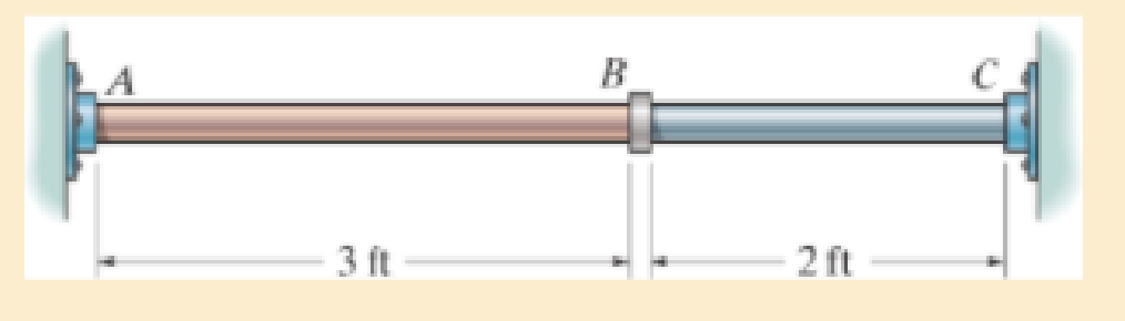
The C83400-red-brass rod AB and 2014-T6- aluminum rod BC are joined at the collar B and fixed connected at their ends. If there is no load in the members when T1=50°F, determine the average normal stress in each member when T2=120°F. Also, how far will the collar be displaced?
The cross-sectional area of each member is 1.75 in2.
Prob. 4–68

Learn your wayIncludes step-by-step video

Chapter 4 Solutions
MECHANICS OF MATERIALS
Additional Engineering Textbook Solutions
Applied Fluid Mechanics (7th Edition)
Automotive Technology: Principles, Diagnosis, And Service (6th Edition) (halderman Automotive Series)
Applied Statics and Strength of Materials (6th Edition)
Thinking Like an Engineer: An Active Learning Approach (4th Edition)
Automotive Technology: Principles, Diagnosis, and Service (5th Edition)
Engineering Mechanics: Dynamics (14th Edition)


- The two cylindrical rod segments are fixed to the rigid walls such that there is a gap of 0.01 in. between them when T1 = 60°F. Each rod has a diameter of 1.25 in. Determine the average normal stress in each rod if T2 = 400 F, and also calculate the new length of the aluminum segment. Take aal = 13(10-6)>°F, Eal = 10(103) ksi, (sY)al = 40 ksi, acu = 9.4(10-6)>°F, (sY)cu = 50 ksi, and Ecu = 15(103) ksiarrow_forwardThe center post B of the assembly has an original length of 123 mm, whereas posts A and C have a length of 127 mm. If the caps on the top and bottom can be considered rigid, determine the average normal stress (in MPa) post A. The posts are made of aluminum and have a cross-sectional area of 423 mm2 Ealuminum = 70 GPa.arrow_forwardThe A-36 steel column, having a cross-sectional area of 10500 mm2, is encased in high-strength concrete as shown. If an axial force of 300kN is applied to the column, determine the compressive stress in the concrete and in the steel. Es = 210GPA and Econc = 29 GPA.arrow_forward
- The aluminum block has a rectangular cross section and is subjected to an axial compressive force of 8 kip. If the 1.5-in. side changed its length to 1.500132 in., determine the Poisson's ratio. Assume modulus of elasticity (E) = 10 x 10^3 ksi indicate the free body diagramarrow_forwardThe center post B of the assembly has an original length of 122 mm, whereas posts A and C have a length of 126 mm. If the caps on the top and bottom can be considered rigid, determine the average normal stress (in MPa) post A. The posts are made of aluminum and have a cross-sectional area of 403 mm2. Ealuminum = 70 GPa. The correct answer is 887.66682. Show solution pls.arrow_forwardThe rigid beam is supported by the three suspender bars. Bars AB and EF are made of aluminum and bar CD is made of steel. If each bar has a cross-sectional area of 450 mm2, determine the maximum value of P if the allowable stress is (sallow)st = 200 MPa for the steel and (sallow)al = 150 MPa for the aluminum. Est = 200 GPa, Eal = 70 GPa.arrow_forward
- The 10-mm-diameter steel bolt is surrounded by a bronze sleeve. The outer diameter of this sleeve is 20 mm, and its inner diameter is 10 mm. If the bolt is subjected to a compressive force of P = 20 kN, determine the average normal stress in the steel and the bronze. Est = 200 GPa, Ebr = 100 GPa.arrow_forwardThe 304 stainless steel post A is surrounded by a red brass C83400 tube B. Both rest on the rigid surface. If a force of 25 kN is applied to the rigid cap, determine the required diameter d of the steel post so that the load is shared equally between the post and tube. The elastic modulus for brass is 101 GPa and the elastic modulus for steel is 193 GPaarrow_forwardThe rigid lever arm is supported by two A-36 steel wires having the same diameter of 4 mm. If a force of P = 3 kN is applied to the handle, determine the force developed in both wires and their corresponding elongations. Consider A-36 steel as an elastic perfectly plastic material.arrow_forward
- The assembly below consists of a steel rod CB and an aluminium rod BA, each having a diameter of 12 mm. If the rod is subjected to the axial loadings at A and at the coupling B, determine the displacement of the coupling B and the end A. The unstretched length of each segment is shown below. Neglect the size of the connections at B and C, and assume that they are rigid. Est = 200 GPa, Eal = 70 GPa.arrow_forwardThe rigid link is supported by a pin at A and two A-36 steel wires, each having an unstretched length of 12 in. and cross-sectional area of 0.0125 in2. Determine the force developed in the wires when the link supports the vertical load of 350 lb.arrow_forwardThe rigid beam is supported by a pin at C and an A-36 steel guy wire AB. If the wire has a diameter of 0.2 in., determine the distributed load w if the end B is displaced 0.75 in. downward.arrow_forward
 Elements Of ElectromagneticsMechanical EngineeringISBN:9780190698614Author:Sadiku, Matthew N. O.Publisher:Oxford University Press
 Mechanics of Materials (10th Edition)Mechanical EngineeringISBN:9780134319650Author:Russell C. HibbelerPublisher:PEARSON
 Thermodynamics: An Engineering ApproachMechanical EngineeringISBN:9781259822674Author:Yunus A. Cengel Dr., Michael A. BolesPublisher:McGraw-Hill Education
 Control Systems EngineeringMechanical EngineeringISBN:9781118170519Author:Norman S. NisePublisher:WILEY
 Mechanics of Materials (MindTap Course List)Mechanical EngineeringISBN:9781337093347Author:Barry J. Goodno, James M. GerePublisher:Cengage Learning
 Engineering Mechanics: StaticsMechanical EngineeringISBN:9781118807330Author:James L. Meriam, L. G. Kraige, J. N. BoltonPublisher:WILEY