
Videos
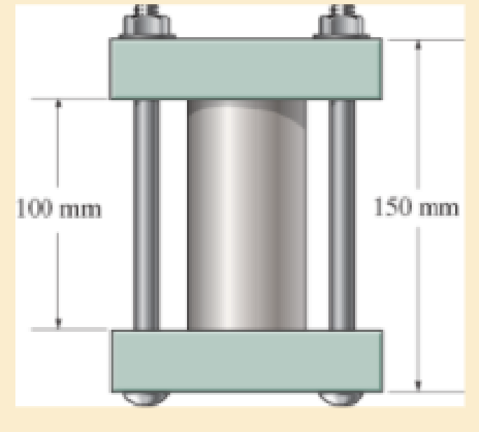
The 50-mm-diameter cylinder is made from Am 1004-T61 magnesium and is placed in the clamp when the temperature is T1=20°C. If the 304-stainless-steel carriage bolts of the clamp each have a diameter of 10 mm, and they hold the cylinder snug with negligible force against the rigid jaws, determine the force in the cylinder when the temperature rises to T2=130°C.

Learn your wayIncludes step-by-step video

Chapter 4 Solutions
Mechanics of Materials-Access
Additional Engineering Textbook Solutions
Statics and Mechanics of Materials (5th Edition)
Automotive Technology: Principles, Diagnosis, and Service (5th Edition)
Thinking Like an Engineer: An Active Learning Approach (3rd Edition)
Automotive Technology: Principles, Diagnosis, And Service (6th Edition) (halderman Automotive Series)
Engineering Mechanics: Statics
Applied Fluid Mechanics (7th Edition)


- The 2014-T6 aluminum rod has a diameter of 0.5 in. and is lightly attached to the rigid supports at A and B when T1 = 70°F. If the temperature becomes T2 = -10°F, and an axial force of P = 16 lb is applied to the rigid collar as shown,determine the reactions at the rigid supports A and B.arrow_forwardThe metal strap has a thickness t and width w and is subjected to a temperature gradient T1 to T2 (T1 6 T2). This causes the modulus of elasticity for the material to vary linearly from E1 at the top to a smaller amount E2 at the bottom. As a result, for any vertical position y, measured from the top surface, E = [(E2 - E1)>w]y + E1. Determine the position d where the axial force P must be applied so that the bar stretches uniformly over its cross-section. warrow_forwardThe 0.35-inch-diameter cylinder is made from C83400 red brass and is placed in the device depicted below when temperature is T1 = 5 oF throughout. The two Am 1004-T-61 magnesium alloy carriage bolts each have a diameter of 0.10 inches and hold the cylinder snug with negligible force against the rigid jaws. Determine the maximum temperature (in oF) that the brass cylinder can be subjected to without causing yielding of any one of the materials. The end plates will not deform or fail.arrow_forward
- A gap of 0.02 in. exists between the composite rod and the wall when the temperature is 75°F. Determine the temperature at which the normal stress in the aluminum rod will be equal to -9 ksi. The temperature of the aluminum rod is _____ °F.arrow_forwardThe bar has a cross-sectional area A, length L, modulus of elasticity E, and coefficient of thermal expansion a. The temperature of the bar changes uniformly along its length from TA at A to TB at B so that at any point x alongthe bar T = TA + x(TB - TA)>L. Determine the force the bar exerts on the rigid walls. Initially, no axial force is in the bar and the bar has a temperature of TA.arrow_forwardThe plastic 50-mm diameter rod is placed in a 51-mm-diameter hole with rigid walls. Determine the change in the length of the rod after the 8 kN load is applied. Use E = 40 MPa and v=0.45 for the rod.arrow_forward
- The spherical gas tank is fabricated by bolting together two hemispherical thin shells. If the 8-m inner diameter tank is to be designed to withstand a gauge pressure of 2 MPa, determine the minimum wall thickness of the tank and the minimum number of 25-mm diameter bolts that must be used to seal it. The tank and the bolts are made from material having an allowable normal stress of 150 MPa and 250 MPa, respectively.arrow_forwardThe rods each have the same 25-mm diameter and 600-mm length. If they are made of A992 steel, determine the forces developed in each rod when the temperature increases by 50 C.arrow_forwardThe cylindrical vessel with hemispherical end caps is made of steel and pressurized to 3.6 MPa. The vessel has a uniform thickness of 18 mm, an outer diameter of 400 mm and effective length of 600 mm. If this vessel is to be replaced with a spherical vessel of equal pressure and equal material strength, determine its thickness.arrow_forward
- The assembly consists of two A992 steel bolts AB and EF and an 6061-T6 aluminum rod CD. When the temperature is at 30° C, the gap between the rod and rigid member AE is 0.1 mm. Determine the normal stress developed in the bolts and the rod if the temperature rises to 130° C. Assume BF is also rigid.arrow_forwardThe assembly has the diameters and material indicated. If it fits securely between its fixed supports when the temperature is T1 = 70°F, determine the average normal stress in each material when the temperature reaches T2 = 110°F.arrow_forwardThe 10-mm-diameter bolt is made of an aluminum alloy. It fits through a magnesium sleeve that has an inner diameter of 15 mm and an outer diameter of 25 mm. The original lengths of the bolt and sleeve are 80 mm and 50 mm, respectively. If after the nut on the bolt is tightened the tension in the bolt is 10 kN, determine the change of volume of the bolt and the new length of the sleeve. Wherein both materials behave linearly elastic. Assume the material at A is rigid. E = 68.9 GPa, Emg = 44.6 GPa, Ga = 26 GPa, Gmg = 18 GPa.arrow_forward
 Elements Of ElectromagneticsMechanical EngineeringISBN:9780190698614Author:Sadiku, Matthew N. O.Publisher:Oxford University Press
 Mechanics of Materials (10th Edition)Mechanical EngineeringISBN:9780134319650Author:Russell C. HibbelerPublisher:PEARSON
 Thermodynamics: An Engineering ApproachMechanical EngineeringISBN:9781259822674Author:Yunus A. Cengel Dr., Michael A. BolesPublisher:McGraw-Hill Education
 Control Systems EngineeringMechanical EngineeringISBN:9781118170519Author:Norman S. NisePublisher:WILEY
 Mechanics of Materials (MindTap Course List)Mechanical EngineeringISBN:9781337093347Author:Barry J. Goodno, James M. GerePublisher:Cengage Learning
 Engineering Mechanics: StaticsMechanical EngineeringISBN:9781118807330Author:James L. Meriam, L. G. Kraige, J. N. BoltonPublisher:WILEY