
Mechanics of Materials-Access
9th Edition
ISBN: 9780133356120
Author: HIBBELER
Publisher: PEARSON
expand_more
expand_more
format_list_bulleted
Concept explainers
Videos
Textbook Question
Chapter 4.9, Problem 4.105P
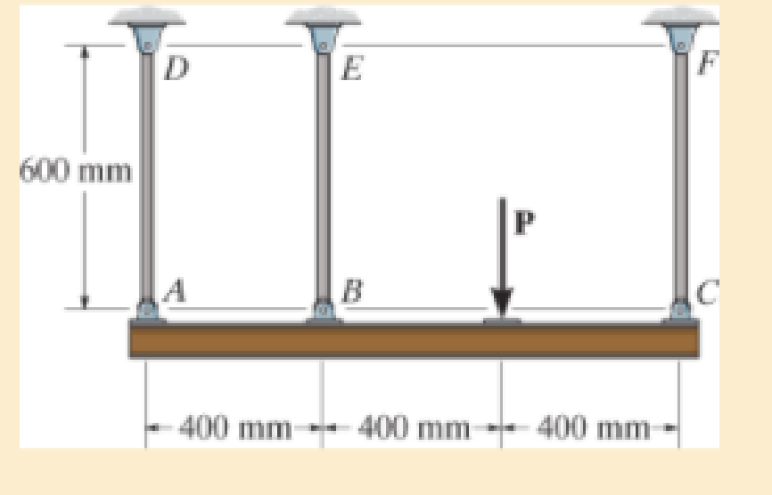
The rigid beam is supported by three 25-mm diameter A-36 steel rods. If the force of P = 230 kN is applied on the beam and removed, determine the residual stresses in each rod. Consider the steel to be an elastic perfectly plastic material.
Prob. 4–105
Expert Solution & Answer
Want to see the full answer?
Check out a sample textbook solution
Students have asked these similar questions
The plate has a thickness of 20 mm and width s = 260 mm. Force P acts along the centerline of this thickness.
Determine the maximum distance d at which the force P can be applied so that it produces no compressive stresses on the plate at section a-a.
The composite shaft, consisting of aluminum, copper, and steel sections, is subjected to the loading shown. Determine the displacement of end A with respect to end D and the normal stress in each section. The cross-sectionalarea and modulus of elasticity for each section are shown in the figure. Neglect the size of the collars at B and C.
The steel pipe has an inner diameter of 2.75 in. and an outer diameter of 3 in. The pipe is fixed at C and subject to the horizontal 20-Ib force acting on the handle of the pipe wrench at its end. Determine The stresses in the pipe acting at point B, which is located on the surface of the pipe. b) The principal stresses acting at this point.c)The absolute maximum shear stress.
Chapter 4 Solutions
Mechanics of Materials-Access
Ch. 4.2 - In each case, determine the internal normal force...Ch. 4.2 - Determine the internal normal force between...Ch. 4.2 - The post weighs 8kN/m. Determine the internal...Ch. 4.2 - The rod is subjected to an external axial force of...Ch. 4.2 - The rigid beam supports the load of 60 kN....Ch. 4.2 - The 20-mm-diameter A-36 steel rod is subjected to...Ch. 4.2 - Segments AB and CD of the assembly are solid...Ch. 4.2 - The 30-mm-diameter A992 steel rod is subjected to...Ch. 4.2 - If the 20-mm-diameter rod is made of A-36 steel...Ch. 4.2 - The 20-mm-diameter 2014-T6 aluminum rod is...
Ch. 4.2 - The 20-mm-diameter 2014-T6 aluminum rod is...Ch. 4.2 - Prob. 4.1PCh. 4.2 - The copper shaft is subjected to the axial loads...Ch. 4.2 - The composite shaft, consisting of aluminum,...Ch. 4.2 - The composite shaft, consisting of aluminum,...Ch. 4.2 - 4-5. The assembly consists of a steel rod CB and...Ch. 4.2 - 4-6. The bar has a cross-sectional area of 3 in2,...Ch. 4.2 - 4–7. If P1 = 50 kip and P2 = 150 kip, determine...Ch. 4.2 - *4-8. If the vertical displacements of end A of...Ch. 4.2 - The assembly consists of two 10-mm diameter red...Ch. 4.2 - The assembly consists of two 10-mm diameter red...Ch. 4.2 - The load is supported by the four 304 stainless...Ch. 4.2 - The load is supported by the four 304 stainless...Ch. 4.2 - The rigid bar is supported by the pin-connected...Ch. 4.2 - Prob. 4.14PCh. 4.2 - Prob. 4.15PCh. 4.2 - *4-16. The hanger consists of three 2014-T6...Ch. 4.2 - 4-17. The hanger consists of three 2014-T6...Ch. 4.2 - Prob. 4.18PCh. 4.2 - Prob. 4.19PCh. 4.2 - The assembly consists of three titanium...Ch. 4.2 - Prob. 4.21PCh. 4.2 - Prob. 4.22PCh. 4.2 - Prob. 4.23PCh. 4.2 - Determine the relative displacement of one end of...Ch. 4.2 - Prob. 4.25PCh. 4.2 - Prob. 4.26PCh. 4.2 - 4-27. The circular bar has a variable radius of r...Ch. 4.2 - Prob. 4.28PCh. 4.2 - Prob. 4.29PCh. 4.2 - Prob. 4.30PCh. 4.5 - 4-31. The concrete column is reinforced using four...Ch. 4.5 - Prob. 4.32PCh. 4.5 - 4-33. The steel pipe is filled with concrete and...Ch. 4.5 - If column AB is made from high strength precast...Ch. 4.5 - If column AB is made from high strength precast...Ch. 4.5 - Determine the support reactions at the rigid...Ch. 4.5 - If the supports at A and C are flexible and have a...Ch. 4.5 - Prob. 4.38PCh. 4.5 - Prob. 4.39PCh. 4.5 - Prob. 4.40PCh. 4.5 - The 2014-T6 aluminum rod AC is reinforced with the...Ch. 4.5 - The 2014-T6 aluminum rod AC is reinforced with the...Ch. 4.5 - The assembly consists of two red brass C83400...Ch. 4.5 - *4-44. The assembly consists of two red brass...Ch. 4.5 - Prob. 4.45PCh. 4.5 - If the gap between C and the rigid wall at D is...Ch. 4.5 - The support consists of a solid red brass C83400...Ch. 4.5 - If there are n fibers, each having a...Ch. 4.5 - Prob. 4.49PCh. 4.5 - Prob. 4.50PCh. 4.5 - Prob. 4.51PCh. 4.5 - Prob. 4.52PCh. 4.5 - 4-53. Each of the three A-36 steel wires has the...Ch. 4.5 - 4-54. The 200-kg load is suspended from three A-36...Ch. 4.5 - The three suspender bars are made of A992 steel...Ch. 4.5 - Prob. 4.56PCh. 4.5 - 4-57. The rigid bar is originally horizontal and...Ch. 4.5 - Prob. 4.58PCh. 4.5 - 4-59. Two identical rods AB and CD each have a...Ch. 4.5 - *4-60. The assembly consists of two posts AD and...Ch. 4.5 - Prob. 4.61PCh. 4.5 - Prob. 4.62PCh. 4.5 - Prob. 4.63PCh. 4.5 - Prob. 4.64PCh. 4.5 - 4-65. Initially the A-36 bolt shank fits snugly...Ch. 4.5 - Prob. 4.66PCh. 4.5 - Prob. 4.67PCh. 4.6 - The C83400-red-brass rod AB and 2014-T6- aluminum...Ch. 4.6 - The assembly has the diameters and material...Ch. 4.6 - The rod is made of A992 steel and has a diameter...Ch. 4.6 - Prob. 4.71PCh. 4.6 - Prob. 4.72PCh. 4.6 - The pipe is made of A992 steel and is connected to...Ch. 4.6 - The bronze C86100 pipe has an inner radius of 0.5...Ch. 4.6 - The 40-ft-long A-36 steel rails on a train track...Ch. 4.6 - The device is used to measure a change in...Ch. 4.6 - The bar has a cross-sectional area A, length L,...Ch. 4.6 - When the temperature is at 30C, the A-36 steel...Ch. 4.6 - When the temperature is at 30C, the A-36 steel...Ch. 4.6 - When the temperature is at 30C, the A-36 steel...Ch. 4.6 - The 50-mm-diameter cylinder is made from Am...Ch. 4.6 - The 50-mm-diameter cylinder is made from Am...Ch. 4.6 - The wires AB and AC are made of steel, and wire AD...Ch. 4.6 - The cylinder CD of the assembly is heated from T1...Ch. 4.6 - The cylinder CD of the assembly is heated from T1=...Ch. 4.6 - The metal strap has a thickness t and width w and...Ch. 4.9 - Determine the maximum normal stress developed in...Ch. 4.9 - If the allowable normal stress for the bar is...Ch. 4.9 - The steel bar has the dimensions shown. Determine...Ch. 4.9 - 4-90. Determine the maximum axial force P that can...Ch. 4.9 - Determine the maximum axial force P that can be...Ch. 4.9 - Determine the maximum normal stress developed in...Ch. 4.9 - Prob. 4.93PCh. 4.9 - 4-94. The resulting stress distribution along...Ch. 4.9 - Prob. 4.95PCh. 4.9 - *4-96. The 10-mm-diameter shank of the steel bolt...Ch. 4.9 - The weight is suspended from steel and aluminum...Ch. 4.9 - The bar has a cross-sectional area of 0.5 in2 and...Ch. 4.9 - Prob. 4.99PCh. 4.9 - *4-100. The rigid beam is supported by a pin at A...Ch. 4.9 - The rigid lever arm is supported by two A-36 steel...Ch. 4.9 - The rigid lever arm is supported by two A-36 steel...Ch. 4.9 - Prob. 4.103PCh. 4.9 - The rigid beam is supported by three 25-mm...Ch. 4.9 - The rigid beam is supported by three 25-mm...Ch. 4.9 - Prob. 4.106PCh. 4.9 - Prob. 4.107PCh. 4.9 - The rigid beam is supported by the three posts A,...Ch. 4.9 - The rigid beam is supported by the three posts A,...Ch. 4.9 - Prob. 4.110PCh. 4.9 - The bar having a diameter of 2 in. is fixed...Ch. 4.9 - Determine the elongation of the bar in Prob.4108...Ch. 4.9 - Prob. 4.113PCh. 4 - The assembly consists of two A992 steel bolts AB...Ch. 4 - The assembly shown consists of two A992 steel...Ch. 4 - The rods each have the same 25-mm diameter and...Ch. 4 - Two A992 steel pipes, each having a...Ch. 4 - The force P is applied to the bar, which is made...Ch. 4 - The 2014-T6 aluminum rod has a diameter of 0.5 in....Ch. 4 - The 2014-T6 aluminum rod has a diameter of 0.5 in....Ch. 4 - The rigid link is supported by a pin at A and two...Ch. 4 - The joint is made from three A992 steel plates...
Knowledge Booster


Learn more about
Need a deep-dive on the concept behind this application? Look no further. Learn more about this topic, mechanical-engineering and related others by exploring similar questions and additional content below.Similar questions
- : The cylindrical pressure vessel with hemispherical end-caps is made of steel. The vessel has a uniform thickness of 0.44mm and an outer diameter of 9.768mm. When the vessel is pressurized to 0.088 MPa, determine the change in the overall length of the vessel. Use E = 200 GPa and µ = 0.3 for steel. Neglect localized bending.R=22arrow_forwardThe distributed loading is applied to the rigid beam, which is supported by the three bars. Each bar has a cross-sectional area of 1.25 in2 and is made from a material having a stress–strain diagram that can be approximated bythe two line segments. If a load of w = 25 kip>ft is applied to the beam, determine the stress in each bar and the vertical displacement of the beam.arrow_forwardThe steel pipe is filled with concrete and subjected to a compressive force of 80 kN. Determine the average normal stress in the concrete and the steel due to this loading. The pipe has an outer diameter of 80 mm and an inner diameter of 70 mm. E 200 GPa, Ec= 24 GPa.arrow_forward
- The shaft is hollow from A to B and solid from B to C. Determine the maximum shear stress in the shaft. The shaft has an outer diameter of 80 mm, and the thickness of the wall of the hollow segment is 10 mm.arrow_forwardThe steel pipe is filled with concrete and subjected to a compressive force of 75 kN. Determine the average normal stress in the concrete due to this loading. The pipe has an outer diameter of 60 mm and an inner diameter of 50 mm. E_s=200 GPa, E_c=24 GPaarrow_forwardThe rigid beam is supported by three 25-mm diameter A-36 steel rods. If the force of P = 230 kN is applied on the beam and removed, determine the residual stresses in each rod. Consider the steel to be an elastic perfectly plastic material.arrow_forward
- The cylindrical pressure vessel with hemispherical end-caps is made of steel. The vessel has a uniform thickness of 0.02R mm and an outer diameter of 0.444R mm. When the vessel is pressurized to 0.004R MPa, determine the change in the overall length of the vessel. Use E = 200 GPa and µ = 0.3 for steel. Neglect localized bending. Note R=993arrow_forwardThe three suspender bars AB, CD, and EF are made of A-36 steel (E = 250 MPa) and have equal cross-sectional areas of 400 mm2. Determine the average normal stress in each bar if the rigid beam is subjected to a force of P = 80 kN. Let d = 3 m and L = 8 marrow_forwardThe strain at point A on the bracket has normal components 250x10-6 and 550x10-6 in x and y directions, respectively and shear component -600 x10-6 in x-y plane. Determine the absolute maximum shear strain in 10-6 unit.arrow_forward
- The assembly is subjected to a tension force P = 2500 N. If these cables are arranged in a parallel assembly as shown, determine the stress of each cable. Cable Length (m) Area (sq. mm.) E (GPa) A 1.4 30 50 B 1.0 10 80 C 1.2 8 60arrow_forwardThe circular punch B exerts a force of 2 kN on the top of the plate A. Determine the average shear stress in the plate due to this loading.arrow_forwardThe A-36 steel bar consists of two segments, one ofcircular cross section of radius r, and one of square crosssection. If the bar is subjected to the axial loading of P,determine the dimensions a of the square segment so thatthe strain energy within the square segment is the same asin the circular segment.arrow_forward
arrow_back_ios
SEE MORE QUESTIONS
arrow_forward_ios
Recommended textbooks for you
 Elements Of ElectromagneticsMechanical EngineeringISBN:9780190698614Author:Sadiku, Matthew N. O.Publisher:Oxford University Press
 Mechanics of Materials (10th Edition)Mechanical EngineeringISBN:9780134319650Author:Russell C. HibbelerPublisher:PEARSON
 Thermodynamics: An Engineering ApproachMechanical EngineeringISBN:9781259822674Author:Yunus A. Cengel Dr., Michael A. BolesPublisher:McGraw-Hill Education
 Control Systems EngineeringMechanical EngineeringISBN:9781118170519Author:Norman S. NisePublisher:WILEY
 Mechanics of Materials (MindTap Course List)Mechanical EngineeringISBN:9781337093347Author:Barry J. Goodno, James M. GerePublisher:Cengage Learning
 Engineering Mechanics: StaticsMechanical EngineeringISBN:9781118807330Author:James L. Meriam, L. G. Kraige, J. N. BoltonPublisher:WILEY
Elements Of Electromagnetics
Mechanical Engineering
ISBN:9780190698614
Author:Sadiku, Matthew N. O.
Publisher:Oxford University Press
Mechanics of Materials (10th Edition)
Mechanical Engineering
ISBN:9780134319650
Author:Russell C. Hibbeler
Publisher:PEARSON
Thermodynamics: An Engineering Approach
Mechanical Engineering
ISBN:9781259822674
Author:Yunus A. Cengel Dr., Michael A. Boles
Publisher:McGraw-Hill Education
Control Systems Engineering
Mechanical Engineering
ISBN:9781118170519
Author:Norman S. Nise
Publisher:WILEY
Mechanics of Materials (MindTap Course List)
Mechanical Engineering
ISBN:9781337093347
Author:Barry J. Goodno, James M. Gere
Publisher:Cengage Learning
Engineering Mechanics: Statics
Mechanical Engineering
ISBN:9781118807330
Author:James L. Meriam, L. G. Kraige, J. N. Bolton
Publisher:WILEY
composite-materials; Author: Tonya Coffey;https://www.youtube.com/watch?v=Vu6ik-bcKf4;License: Standard youtube license