
Concept explainers
Videos
a)
Show that the maximum compressive stresses are in the ratio 4:5:7:9.
a)
Explanation of Solution
Given information:
The load act on the point of the bars is P.
Calculation:
At the point A:
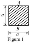
Show the cross-sectional diagram of the square bar as in Figure 1.
Here,
Refer to Figure 1.
The maximum compressive stress of the square bar
Here, e is the eccentricity of the load and
The cross-sectional area of the square bar
The eccentricity of the load (e) is
The distance between the centroid from extreme fibre
The moment of inertia
Calculate the maximum compressive stress of the square bar
Substitute
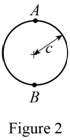
Show the cross-sectional diagram of the circular bar as in Figure 2.
Here,
Refer to Figure 2.
The maximum compressive stress of the circular bar
The cross-sectional area of the circular bar
The eccentricity of the load (e) is
The distance between the centroid from extreme fibre
The moment of inertia
Calculate the maximum compressive stress of the circular bar
Substitute
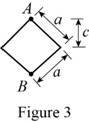
Show the cross-sectional diagram of the diamond shape bar as in Figure 3.
Here,
Refer to Figure 3.
The maximum compressive stress of the diamond shape bar
The cross-sectional area of the diamond shape bar
The eccentricity of the load (e) is
The distance between the centroid from extreme fibre
The moment of inertia
Calculate the maximum compressive stress of the diamond shape bar
Substitute
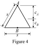
Show the cross-sectional diagram of the triangular bar as in Figure 4.
Here,
Refer to Figure 4.
The maximum compressive stress of the triangular bar
The cross-sectional area of the triangular bar
The distance between the centroid from extreme fibre
The eccentricity of the load (e) is
The moment of inertia
Calculate the maximum compressive stress of the triangular bar
Substitute
Calculate the maximum compressive stresses are in the ratio:
Substitute
The four bars shown have the same cross-sectional area.
Hence the maximum compressive stresses are in the ratio 4:5:7:9 is proved.
b)
Show that the maximum tensile stresses are in the ratio 2:3:5:3.
b)
Explanation of Solution
Given information:
The load act on the point of the bars is P.
Calculation:
At the point B:
Refer to Figure 1.
The maximum tensile stress of the square bar
Here, the e is the eccentricity of the load and
The cross-sectional area of the square bar
The eccentricity of the load (e) is
The distance between the centroid from extreme fibre
The moment of inertia
Calculate the maximum tensile stress of the square bar
Substitute
Refer to Figure 2.
The maximum tensile stress of the circular bar
The cross-sectional area of the circular bar
The eccentricity of the load (e) is
The distance between the centroid from extreme fibre
The moment of inertia
Calculate the maximum tensile stress of the circular bar
Substitute
Refer to Figure 3.
The maximum tensile stress of the diamond shape bar
The cross-sectional area of the diamond shape bar
The eccentricity of the load (e) is
The distance between the centroid from extreme fibre
The moment of inertia
Calculate the maximum tensile stress of the diamond shape bar
Substitute
Refer to Figure 4.
The maximum tensile stress of the triangular bar
The cross-sectional area of the triangular bar
The distance between the centroid from extreme fibre
The eccentricity of the load (e) is
The moment of inertia
Calculate the maximum tensile stress of the triangular bar
Substitute
Calculate the maximum tensile stresses are in the ratio:
Substitute
The four bars shown have the same cross-sectional area.
Hence the maximum tensile stresses are in the ratio 2:3:5:3 is proved.
Want to see more full solutions like this?
Chapter 4 Solutions
EBK MECHANICS OF MATERIALS


- A fabric used in air-inflated structures is subjected to a biaxial load-ing that results in normal stresses σx=120 MPa and σz =160 MPa. Knowing that the properties of the fabric can be approximated as E=87 GPa and ν= 0.34, determine the change in length of (a) side AB, (b) side BC, (c) diagonal AC.arrow_forwardTo determine the state of stress in a solid rod using the principle of superposition. A solid rod has a diameter of e� = 55 mmmm and is subjected to the loading shown. Let a� = 200 mmmm , b� = 220 mmmm , c� = 350 mmmm , d� = 250 mmmm , and P� = 3.0 kNkN . Take point A to be at the top of the circular cross-section. As shown (Figure 2), a cut was made at A to determine the resultant internal loadings. Determine the moment about the x axis, Mx��. b) Part B - Moment about the z axis at A Part C - Stress due to the normal force To find the state of stress at A, the principle of superposition must be used. If the rod has a diameter of 55 mm , find the stress σA�� due to the normal force. Part D - Stress due to the bending moment about the x axis To find the state of stress at A, the principle of superposition must be used. If the rod has a diameter of 55 mm , find the stress σA�� due to the bending moment about the x axis.arrow_forwardTwo solid cylindrical rods AB and BC are welded together at B and loaded as shown. Knowing that d1 = 50 mm and d2 = 30 mm, find the average normal stress at the midsection of (a) rod AB, (b) rod BC.arrow_forward
- Two solid cylindrical rods AB and BC are welded together at B and loaded as shown. Knowing that d1 = 30 mm and d2=50 mm,find the average normal stress at the midsection of (a) rod AB,(b) rod BC.arrow_forwardIn many situations physical constraints prevent strain from occurring in a given direction. For example, εz= 0 in the case shown, where longitudinal movement of the long prism is prevented at every point. Plane sections perpendicular to the longitudinal axis remain plane and the same distance apart. Show that for this situation, which is known as plane strain, we can express σz, εx, and εy as followsarrow_forwardA timber beam AB of length L and rectangular cross section carries a single concentrated load P at its midpoint C. (a) Show that the ratio Tm/ m of the maximum values of the shearing and normal stresses in the beam is equal to h/2L, where h and L are, respectively, the depth and the length of the beam. (b) Determine the depth h and the width b of the beam, knowing that L = 2 m, P = 40 kN, 7m = 960 kPa, and om = 12 MPa.arrow_forward
- Two brass rods AB and BC, each of uniform diameter, will be brazed together at B to form a nonuniform rod of total length 100 m, which will be suspended from a support at A as shown. The density of brass is 8470 kg/m^3 Determine normal stresses of ((σzz)AB and (σzz)BC) as a function of z, and draw the variation of stresses with respect to z-axis on the same graph.arrow_forwardA rigid bar AB of length L = 1600 mm is hinged to a support at A and supported by two vertical wires attached at points C and D such that AC = 500mm and AD = 1200mm Both the wires have same cross sectional area of 16 mm² and made of the same material having Young's modulus of 200 GPa. The wire at C has a length of 400 mm and that at D has 800 mm. Determine the tensile stresses in the wires and downward displacement at point B of the bar when a load of 1 kN is suspended at B.arrow_forwardThe structure shown consists of a single member ABCDE with a pin support at A and a roller support at E. Points B and D are at the midpoints of their respective segments. Determine the internal shear force acting on I which are located immediately to the left of C. Take N = 1 kN, O = 3 kN, and P = 4 kN.arrow_forward
- A rod must not stretch more than 6 mm when the tension in the wire is 8 kN. Knowing that E = 105 GPa and that the maximum allowable normal stress is 150 MPa, determine the corresponding maximum length of the rod (m).arrow_forwardA 1600-lb-in. couple is applied to a wooden beam, of rectangular cross section 1.5 by 3.5 in., in a plane forming an angle of 308 with the vertical (Fig. ). Determine (a) the maximum stress in the beam and (b) the angle that the neutral surface forms with the horizontal planearrow_forwardStraight rods of 0.30-in. diameter and 200-ft length are sometimes used to clear underground conduits of obstructions or to thread wires through a new conduit. The rods are made of high-strength steel and, for storage and transportation, are wrapped on spools of 5-ft diameter. Assuming that the yield strength is not exceeded, determine (a) the maximum stress in a rod, when the rod, which was initially straight, is wrapped on the spool, (b) the corresponding bending moment in the rod. Use E= 29 * 106 psi.arrow_forward
 Elements Of ElectromagneticsMechanical EngineeringISBN:9780190698614Author:Sadiku, Matthew N. O.Publisher:Oxford University Press
 Mechanics of Materials (10th Edition)Mechanical EngineeringISBN:9780134319650Author:Russell C. HibbelerPublisher:PEARSON
 Thermodynamics: An Engineering ApproachMechanical EngineeringISBN:9781259822674Author:Yunus A. Cengel Dr., Michael A. BolesPublisher:McGraw-Hill Education
 Control Systems EngineeringMechanical EngineeringISBN:9781118170519Author:Norman S. NisePublisher:WILEY
 Mechanics of Materials (MindTap Course List)Mechanical EngineeringISBN:9781337093347Author:Barry J. Goodno, James M. GerePublisher:Cengage Learning
 Engineering Mechanics: StaticsMechanical EngineeringISBN:9781118807330Author:James L. Meriam, L. G. Kraige, J. N. BoltonPublisher:WILEY