
Shigley's Mechanical Engineering Design (McGraw-Hill Series in Mechanical Engineering)
10th Edition
ISBN: 9780073398204
Author: Richard G Budynas, Keith J Nisbett
Publisher: McGraw-Hill Education
expand_more
expand_more
format_list_bulleted
Concept explainers
Videos
Textbook Question
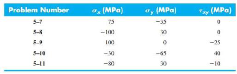
Chapter 5, Problem 11P
5-7 to 5-11 An AISI 1018 steel has a yield strength, Sy = 295 MPa. Using the distortion-energy theory for the given state of plane stress, (a) determine the factor of safety, (b) plot the failure locus, the load line, and estimate the factor of safety by graphical measurement.
Expert Solution & Answer
Want to see the full answer?
Check out a sample textbook solution
Students have asked these similar questions
The figure shows a section of a shaft made of annealed steel with yield strength of 600 MPa and ultimate tensile strength of 700 MPa. Diameters of the shaft are D=30 mm and d=20 mm. Fillet radius of the shoulder section is 2.5 mm. The shaft is rotating and subjected to steady bending moment of M=51 Nm, steady torsion of T=58 Nm and steady axial load of F=14 kN. The operating temperature of the shaft is 20 ᵒC and reliability is 99%. The shaft has ground surface.Calculate the mean component of the shear stress (in MPa)
The figure shows a section of a shaft made of annealed steel with yield strength of 600 MPa and ultimate tensile strength of 700 MPa. Diameters of the shaft are D=30 mm and d=20 mm. Fillet radius of the shoulder section is 2.5 mm. The shaft is rotating and subjected to steady bending moment of M=51 Nm, steady torsion of T=58 Nm and steady axial load of F=14 kN. The operating temperature of the shaft is 20 ᵒC and reliability is 99%. The shaft has ground surface.
Calculate the alternating component of the normal stress (in MPa). (If there is no alternating component of the normal stress, enter "0" in the answer box)
The cold-drawn AISI 1040 Q&T at 205 ◦C steel bar shown in the figure is subjected to a completely reversed axial load fluctuating between 28 kN in compression to 28 kN in tension. Estimate the fatigue factor of safety based on achieving infinite life, and the yielding factor of safety for the following cases. If infinite life is not predicted, estimate the number of cycles to failure.a) for the part given in Fig 2(a) and b) for the part given in Fig. 2 (b) using the same dimensions (W=25mm, r=3mm, the thickness of 10 mm)
Chapter 5 Solutions
Shigley's Mechanical Engineering Design (McGraw-Hill Series in Mechanical Engineering)
Ch. 5 - A ductile hot-rolled steel bar has a minimum yield...Ch. 5 - A ductile hot-rolled steel bar has a minimum yield...Ch. 5 - A ductile hot-rolled steel bar has a minimum yield...Ch. 5 - A ductile hot-rolled steel bar has a minimum yield...Ch. 5 - A ductile hot-rolled steel bar has a minimum yield...Ch. 5 - Prob. 6PCh. 5 - 5-7 to 5-11 An AISI 1018 steel has a yield...Ch. 5 - 5-7 to 5-11 An AISI 1018 steel has a yield...Ch. 5 - 5-7 to 5-11 An AISI 1018 steel has a yield...Ch. 5 - 5-7 to 5-11 An AISI 1018 steel has a yield...
Ch. 5 - 5-7 to 5-11 An AISI 1018 steel has a yield...Ch. 5 - A ductile material has the properties Syt = 60...Ch. 5 - Prob. 13PCh. 5 - Prob. 14PCh. 5 - Prob. 15PCh. 5 - 5-14 to 5-18 An AISI 4142 steel QT at 800F...Ch. 5 - 5-14 to 5-18 An AISI 4142 steel QT at 800F...Ch. 5 - 5-14 to 5-18 An AISI 4142 steel QT at 800F...Ch. 5 - A brittle material has the properties Sut = 30...Ch. 5 - Repeat Prob. 519 by first plotting the failure...Ch. 5 - For an ASTM 30 cast iron, (a) find the factors of...Ch. 5 - For an ASTM 30 cast iron, (a) find the factors of...Ch. 5 - Prob. 23PCh. 5 - For an ASTM 30 cast iron, (a) find the factors of...Ch. 5 - 5-21 to 5-25 For an ASTM 30 cast iron, (a) find...Ch. 5 - 5-26 to 5-30 A cast aluminum 195-T6 exhibits Sut =...Ch. 5 - 5-26 to 5-30 A cast aluminum 195-T6 exhibits Sut =...Ch. 5 - 5-26 to 5-30 A cast aluminum 195-T6 exhibits Sut =...Ch. 5 - 5-26 to 5-30 A cast aluminum 195-T6 exhibits Sut =...Ch. 5 - 5-26 to 5-30 A cast aluminum 195-T6 exhibits Sut =...Ch. 5 - 5-31 to 5-35 Repeat Probs. 526 to 530 using the...Ch. 5 - 5-31 to 5-35 Repeat Probs. 526 to 530 using the...Ch. 5 - Repeat Probs. 526 to 530 using the modified-Mohr...Ch. 5 - Repeat Probs. 526 to 530 using the modified-Mohr...Ch. 5 - Repeat Probs. 526 to 530 using the modified-Mohr...Ch. 5 - This problem illustrates that the factor of safety...Ch. 5 - For the beam in Prob. 344, p. 147, determine the...Ch. 5 - A 1020 CD steel shaft is to transmit 20 hp while...Ch. 5 - For the problem specified in the table, build upon...Ch. 5 - For the problem specified in the table, build upon...Ch. 5 - 5-39 to 5-55 For the problem specified in the...Ch. 5 - Prob. 42PCh. 5 - For the problem specified in the table, build upon...Ch. 5 - For the problem specified in the table, build upon...Ch. 5 - Prob. 45PCh. 5 - 5-39 to 5-55 For the problem specified in the...Ch. 5 - Prob. 47PCh. 5 - For the problem specified in the table, build upon...Ch. 5 - For the problem specified in the table, build upon...Ch. 5 - For the problem specified in the table, build upon...Ch. 5 - For the problem specified in the table, build upon...Ch. 5 - 5-39 to 5-55 For the problem specified in the...Ch. 5 - 5-39 to 5-55 For the problem specified in the...Ch. 5 - For the problem specified in the table, build upon...Ch. 5 - For the problem specified in the table, build upon...Ch. 5 - Build upon the results of Probs. 384 and 387 to...Ch. 5 - Using F = 416 lbf, design the lever arm CD of Fig....Ch. 5 - A spherical pressure vessel is formed of 16-gauge...Ch. 5 - This problem illustrates that the strength of a...Ch. 5 - Prob. 60PCh. 5 - A cold-drawn AISI 1015 steel tube is 300 mm OD by...Ch. 5 - Prob. 62PCh. 5 - The figure shows a shaft mounted in bearings at A...Ch. 5 - By modern standards, the shaft design of Prob. 563...Ch. 5 - Build upon the results of Prob. 340, p. 146, to...Ch. 5 - For the clevis pin of Prob. 340, p. 146, redesign...Ch. 5 - A split-ring clamp-type shaft collar is shown in...Ch. 5 - Prob. 68PCh. 5 - Prob. 69PCh. 5 - Prob. 70PCh. 5 - Two steel tubes have the specifications: Inner...Ch. 5 - Repeal Prob. 5-71 for maximum shrink-fit...Ch. 5 - Prob. 73PCh. 5 - Two steel lubes are shrink-filled together where...Ch. 5 - Prob. 75PCh. 5 - Prob. 76PCh. 5 - Prob. 77PCh. 5 - Prob. 78PCh. 5 - Prob. 79PCh. 5 - Prob. 80PCh. 5 - Prob. 81PCh. 5 - For Eqs. (5-36) show that the principal stresses...Ch. 5 - Prob. 83PCh. 5 - A plate 100 mm wide, 200 mm long, and 12 mm thick...Ch. 5 - A cylinder subjected to internal pressure pi has...
Knowledge Booster


Learn more about
Need a deep-dive on the concept behind this application? Look no further. Learn more about this topic, mechanical-engineering and related others by exploring similar questions and additional content below.Similar questions
- Two sections of steel drill pipe, joined by bolted flange plates at Ä are being tested to assess the adequacy of both the pipes. In the test, the pipe structure is fixed at A, a concentrated torque of 500 kN - m is applied at x = 0.5 m, and uniformly distributed torque intensity t1= 250 kN m/m is applied on pipe BC. Both pipes have the same inner diameter = 200 mm. Pipe AB has thickness tAB=15 mm, while pipe BC has thickness TBC= 12 mm. Find the maximum shear stress and maximum twist of the pipe and their locations along the pipe. Assume G = 75 GPa.arrow_forwardProduced from xCy steel material by machining method, the shaft is bedded at C and D points. With the shaft, constant Fy= 820 N forces in the vertical direction and constant Fx= 4,2 kN forces in the axial direction, which do not rotate together. The tensile strength of the shaft material is (sigma)tensile = (sigma)ut = 620 MPa and the yield strength is (sigma)yield = 420 MPa. For 50% reliability, analyze the fatigue damage condition of the shaft sections A and B separately.arrow_forwardThe figure shows a shaft mounted in bearings at A and D and having pulleys at B and C. The forces shown acting on the pulley surfaces represent the belt tensions. The shaft is to be made of AISI 1035 CD steel. Using distortion-energy theory with a design factor of 2, determine the minimum shaft diameter to avoid yielding.arrow_forward
- The rotating shaft running at n = 900 rpm, shown in the figure below, is machined from AISI 1045 CD steel. It is subjected to a force of F = 10.1 kN. The shaft is experiencing an operating temperature of 35 oC. With the specified loading and for the reliability of 99.9 %, Determine the minimum factor of safety for fatigue based on infinite life*. Determine the maximum safe load (Fmax) that can be applied for a factor of safety of 1.5 and a design life of 5x10⁵ cycles, all other input values remaining the same. Determine the factor of safety against yielding.arrow_forwardA bar AISI 1035 steel forged and heat treated with minimum yield strength of 570MPa is subjected to bending moment of 290Nm and a torsional moment of 310Nm. Assuming a factor of safety of 2, determine the diameter of rod using the following theories of failure (i) Maximum Shear stress theory and (ii) Distortion Energy theory (iii) Maximum stress theory, also specify which diameter is considered as safearrow_forwardAn ASTM cast iron, grade 30, has ultimate strength at tension Sut = 406 MPa, and at compression Suc = 996 MPa. it carries static loading resulting in the following principle stress σA = 138 MPa , σB = -241 MPa. Choose the appropriate failure theory and estimate the factor of safety.arrow_forward
- A bracket is under a loading condition shown below. It's made from a steel with yield strength (Sy) of 42 ksi and ultimate tensile strength (Sut) of 76 ksi. The diameter is 0.42 in and b = 1.75 in, with the load P fluctuate between 15 lbs (tension) and -5 lbs (compression). Using the modified Goodman or Gerber criterion, determine the fatigue factor of safety based on infinite life. If infinite life is not predicted, estimate the number of cycles to failure. Also check for yielding.arrow_forwardThe stresses on the surface of a hard bronze component are shown in the figure below. The yield strength of the bronze is σY = 345 MPa.a) What is the factor of safety predicted by the maximum-shear-stress theory of failure for the stress state shown? Does the component fail according to this theory?b) What is the value of the Mises equivalent stress for the given state of plane stress?c) What is the factor of safety predicted by the failure criterion of the maximum-distortion energy theory of failure? Does the component fail according to this theory?arrow_forward1. A part made of Aluminum 6061-T6 has a yield strength = 400 MPa. For each stress state below, draw all 3 Mohr's circles, find the principal stresses, and calculate the safety factor against yield using both the distortion-energy (von Mises) and maximum shear stress (Tresca) criterions. (If relevant) A clearly labeled diagram (or diagrams) clearly pertaining to your analysis with a coordinate system and relevant labels. Final answer with appropriate units and significant figures. You can use the fprintf() command in MATLAB to format numerical results A 2-3 sentence reflection on your answer. Does it make sense? Why or why not? What are some implications?arrow_forward
- A Steel shaft is subjected to an end thrust producing a stress of 90 MPa and the minimum shearing stress on the surface arising from torsion is 60 MPa .The yield point stress of the material in simple tension was found to be 300 MPa. calculate the factor of safety of the shaft according to the following theory 1)maximum shear stress theoryarrow_forwardA helical compression spring is made of a specialty alloy wire with a wire diameter d = 4 mm and an inner coil diameter Di = 18 mm. For this type of alloy and specified wire diameter, the shear yield strength is 715 MPa and the modulus of rigidity is 77.2 GPa. If the spring has 9 active coils, determine the factor of safety nd when the spring deflection is 7 mm.arrow_forwardA screw clamp shown in the figure has a handle with diameter 5 mm made of cold-drawn AISI 1006 steel (table E18 - page 1195). The overall length of the hand is 75 mm. The screw is M 12 coarse (table 8-1) and is 145 mm long, overall. Distance A is 50 mm. The clamp will accommodate parts up to 105 mm high.a) What is the value of screw torque that causes the handle to bend permanently?b) If the collar friction is neglected and if the thread friction is 0.075, what is the screw force value that causes the handle to bend permanently?c) What is the value of clamping force, which will cause the screw to buckle?d) Are there any other stresses or possible failures to be checked?e) If yes, calculate them.arrow_forward
arrow_back_ios
SEE MORE QUESTIONS
arrow_forward_ios
Recommended textbooks for you
 Mechanics of Materials (MindTap Course List)Mechanical EngineeringISBN:9781337093347Author:Barry J. Goodno, James M. GerePublisher:Cengage Learning
Mechanics of Materials (MindTap Course List)
Mechanical Engineering
ISBN:9781337093347
Author:Barry J. Goodno, James M. Gere
Publisher:Cengage Learning
Material Properties 101; Author: Real Engineering;https://www.youtube.com/watch?v=BHZALtqAjeM;License: Standard YouTube License, CC-BY