
Concept explainers
Videos
Given the op amp circuit shown in Fig. 5.72, express vo in terms of v1 and v2.
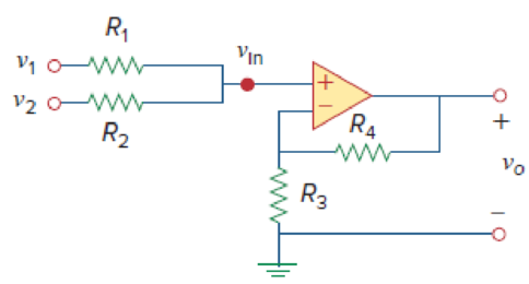
Figure 5.72
For Prob. 5.34.
State the expression for the voltage
Answer to Problem 34P
The expression for the voltage
Explanation of Solution
Given data:
Refer Figure 5.72 in the textbook for the op amp circuit.
Calculation:
Consider that the given circuit is a non-inverting amplifier.
Modify to the Figure 5.72 by indicating the node voltage
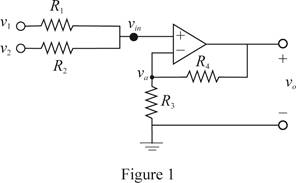
In Figure 1, write the expression by the use of Kirchhoff's current law.
Re-arrange the equation.
Consider the expression for the voltage
Substitute
Consider the expression for voltage
Re-arrange equation (2).
Multiply
Substitute equation (3) in (4).
Conclusion:
Thus, the expression for the voltage
Want to see more full solutions like this?
Chapter 5 Solutions
Fundamentals of Electric Circuits


- The op amp in the circuit shown is ideal. Calculate vo if va=2 V and vb=1 V.arrow_forwardBased on the op amp circuit in Figure, answer the following questions,assuming an ideal op-amp. Given:V1 = 1 VI2 = 2 mAV3 = 0.5 VRa = 2 kΩRb = 1 kΩRc = 5 kΩRd = 10 kΩVx = 4VIb = 3.5mANow I need to determine Vo and the current and power through Rd.Please help, Thank youarrow_forwardCalculate the voltage ratio vo/vs for the op amp circuit of Fig. 5.51. Assume that the op amp is ideal.arrow_forward
- 6. Which of the following characteristics does not necessarily apply to an op amp?to. high gainb. High input impedancec. High powerd. Low output impedancearrow_forwardThe op amp shown below has a maximum output voltage range from −5 to +5 V. The maximum output current magnitude of the op amp is 20 mA. The slew-rate limit is 5 V/μs. a. Find the full-power bandwidth of the op amparrow_forwardAn op-amp with an open-loop gain of 3x10⁶ and Vcc = 12 V has an inverting-input voltage of 6.7 microVolts and a non-inverting input voltage of 5.4 microVolts. What is its output voltage? Be sure to round your answer to the nearest single digital decimal place. Do not enter units. As an example, if you calculate 7.39 Volts then enter 7.4 as your submitted answerarrow_forward
- Calculate the output voltage of an op-amp summing amplifier for the followingsets, consider Rf=1Mna. V1=+1v, V2=+2v, V3=+3v, Ri=R2, R3=500Ω b. V1=+1v, V2=+2v, V3=+3v, Ri-500kΩ, R2=1MΩ, R3=1MΩarrow_forwardDetermine v0 and i0 in the Cascaded Op-Amp circuit belowarrow_forwardDetermine the output voltage of an op amp amplifier circuit with the following parameters: Differential voltage gain = 4522CMRR = 631Vi1 = 659 mV Vi2 = 659 mV Vi1 and Vi2 are in phase and have the same frequency. \ QUICKLYarrow_forward
- In the ideal operational amplifier circuit given in Figure 5, a) Find the voltage V0. B) Find the current I0. Y=3arrow_forwardIn the op-amp circuit shown below, find V0. 30 kQ Select one: O avo=6V O b.vo=3v c. None of the above ) d.VO=9Varrow_forward1. For the circuit shown, show that if ΔR<<R, the output voltage of the op amp is approximately vo≈Rf(R+Rf)R2(R+2Rf)(−ΔR)vin. 2. Find vo if Rf=470 kΩ, R=10 kΩ, ΔR=95 Ω, and vin=15 V. 3. Find the actual value of vo in (b).arrow_forward
 Introductory Circuit Analysis (13th Edition)Electrical EngineeringISBN:9780133923605Author:Robert L. BoylestadPublisher:PEARSON
 Delmar's Standard Textbook Of ElectricityElectrical EngineeringISBN:9781337900348Author:Stephen L. HermanPublisher:Cengage Learning
 Programmable Logic ControllersElectrical EngineeringISBN:9780073373843Author:Frank D. PetruzellaPublisher:McGraw-Hill Education
 Fundamentals of Electric CircuitsElectrical EngineeringISBN:9780078028229Author:Charles K Alexander, Matthew SadikuPublisher:McGraw-Hill Education
 Electric Circuits. (11th Edition)Electrical EngineeringISBN:9780134746968Author:James W. Nilsson, Susan RiedelPublisher:PEARSON
 Engineering ElectromagneticsElectrical EngineeringISBN:9780078028151Author:Hayt, William H. (william Hart), Jr, BUCK, John A.Publisher:Mcgraw-hill Education,