
Fundamentals of Electric Circuits
6th Edition
ISBN: 9780078028229
Author: Charles K Alexander, Matthew Sadiku
Publisher: McGraw-Hill Education
expand_more
expand_more
format_list_bulleted
Concept explainers
Videos
Textbook Question
Chapter 5.2, Problem 1PP
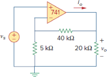
If the same 741 op amp in Example 5.1 is used in the circuit of Fig. 5.7, calculate the closed-loop gain vo/vs. Find io when vs = 1 V.
Figure 5.7
Expert Solution & Answer
Want to see the full answer?
Check out a sample textbook solution
Students have asked these similar questions
If they are defined as R1=12Ω, R2=5Ω and VS=5V respectively in the circuit given below, how many amps is the İ1 ambient current value?
Help me please... Thank you so much.
Q1:A: Design a multi-range ammeter of 0.5 and 1 Amp. using a PMMC(galvanometer) of 50Ω internal resistance and full-scale current of 1 ma. Show the way of connection with the load RL.
5.40 Referring to the circuit shown in Fig. 5.77, determine Vo in terms of V1 and V2.
Chapter 5 Solutions
Fundamentals of Electric Circuits
Ch. 5.2 - If the same 741 op amp in Example 5.1 is used in...Ch. 5.3 - Repeat Example 5.1 using the ideal op amp model....Ch. 5.4 - Practice Problem 5.3 Figure 5.13 For Practice...Ch. 5.4 - Two kinds of current-to-voltage converters (also...Ch. 5.5 - Calculate vo in the circuit of Fig. 5.20. Answer:...Ch. 5.6 - Practice Problem 5.6 Find vo and io in the op amp...Ch. 5.7 - Design a difference amplifier with gain 7.5....Ch. 5.7 - Obtain io in the instrumentation amplifier circuit...Ch. 5.8 - Practice Problem 5.9 Figure 5.30 For Practice...Ch. 5.8 - If v1 = 5 V and v2 = 5 V, find vo in the op amp...
Ch. 5.9 - Rework Practice Prob. 5.1 using PSpice. If the...Ch. 5.10 - A three-bit DAC is shown in Fig. 5.37. (a)...Ch. 5.10 - Determine the value of the external gain-setting...Ch. 5 - The two input terminals of an op amp are labeled...Ch. 5 - For an ideal op amp, which of the following...Ch. 5 - For the circuit in Fig. 5.40, voltage vo is: (a)6...Ch. 5 - For the circuit in Fig. 5.40, current ix is:...Ch. 5 - If vs = 0 in the circuit of Fig. 5.41, current io...Ch. 5 - If vs = 8 mV in the circuit of Fig. 5.41, the...Ch. 5 - Refer to Fig. 5.41. If vs = 8 mV, voltage va is:...Ch. 5 - The power absorbed by the 4-k resistor in Fig....Ch. 5 - Which of these amplifiers is used in a...Ch. 5 - Difference amplifiers are used in (please check...Ch. 5 - The equivalent model of a certain op amp is shown...Ch. 5 - The open-loop gain of an op amp is 50,000....Ch. 5 - Determine the voltage input to the inverting...Ch. 5 - The output voltage of an op amp is 4 V when the...Ch. 5 - For the op amp circuit of Fig. 5.44, the op amp...Ch. 5 - Using the same parameters for the 741 op amp in...Ch. 5 - 5.7 The op amp in Fig. 5.46 has Ri = 100 k, Ro =...Ch. 5 - Obtain vo for each of the op amp circuits in Fig....Ch. 5 - Determine vo for each of the op amp circuits in...Ch. 5 - Prob. 10PCh. 5 - Using Fig. 5.50, design a problem to help other...Ch. 5 - Calculate the voltage ratio vo/vs for the op amp...Ch. 5 - Find vo and io in the circuit of Fig. 5.52. Figure...Ch. 5 - Determine the output voltage vo in the circuit of...Ch. 5 - (a)Determine the ratio vo/is in the op amp circuit...Ch. 5 - Using Fig. 5.55, design a problem to help students...Ch. 5 - Prob. 17PCh. 5 - For the circuit shown in Figure 5.57, solve for...Ch. 5 - Determine io in the circuit of Fig. 5.58. Figure...Ch. 5 - In the circuit of Fig. 5.59, calculate vo of vs =...Ch. 5 - Calculate vo in the op amp circuit of Fig. 5.60....Ch. 5 - Design an inverting amplifier with a gain of 15.Ch. 5 - For the op amp circuit in Fig. 5.61, find the...Ch. 5 - In the circuit shown in Fig. 5.62, find k in the...Ch. 5 - Calculate vo in the op amp circuit of Fig. 5.63....Ch. 5 - Using Fig. 5.64, design a problem to help other...Ch. 5 - Find vo in the op amp circuit of Fig. 5.65. Figure...Ch. 5 - Prob. 28PCh. 5 - Determine the voltage gain vo/vi of the op amp...Ch. 5 - In the circuit shown in Fig. 5.68, find ix and the...Ch. 5 - For the circuit in Fig. 5.69, find ix. Figure 5.69...Ch. 5 - Calculate ix and vo in the circuit of Fig. 5.70....Ch. 5 - Refer to the op amp circuit in Fig. 5.71....Ch. 5 - Given the op amp circuit shown in Fig. 5.72,...Ch. 5 - Design a noninverting amplifier with a gain of...Ch. 5 - For the circuit shown in Fig. 5.73, find the...Ch. 5 - Determine the output of the summing amplifier in...Ch. 5 - Using Fig. 5.75, design a problem to help other...Ch. 5 - For the op amp circuit in Fig. 5.76, determine the...Ch. 5 - Referring to the circuit shown in Fig. 5.77,...Ch. 5 - An averaging amplifier is a summer that provides...Ch. 5 - The feedback resistor of a three-input averaging...Ch. 5 - The feedback resistor of a five-input averaging...Ch. 5 - Show that the output voltage vo of the circuit in...Ch. 5 - Design an op amp circuit to perform the following...Ch. 5 - Using only two op amps, design a circuit to solve...Ch. 5 - The circuit in Fig. 5.79 is for a difference...Ch. 5 - The circuit in Fig. 5.80 is a differential...Ch. 5 - Design a difference amplifier to have a gain of 4...Ch. 5 - Design a circuit to amplify the difference between...Ch. 5 - Using two op amps, design a subtractor.Ch. 5 - Design an op amp circuit such that vo = 4v1 + 6v2 ...Ch. 5 - The ordinary difference amplifier for fixed-gain...Ch. 5 - Determine the voltage transfer ratio vovs in the...Ch. 5 - In a certain electronic device, a three-stage...Ch. 5 - Using Fig. 5.83, design a problem to help other...Ch. 5 - Find vo in the op amp circuit of Fig. 5.84.Ch. 5 - Calculate io in the op amp circuit of Fig. 5.85....Ch. 5 - In the op amp circuit of Fig. 5.86, determine the...Ch. 5 - Calculate vo/vi in the op amp circuit of Fig....Ch. 5 - Determine vo in the circuit of Fig. 5.88. Figure...Ch. 5 - Obtain the closed-loop voltage gain vo/vi of the...Ch. 5 - Determine the gain vovi of the circuit in Fig....Ch. 5 - For the op amp circuit shown in Fig. 5.91, find...Ch. 5 - Find vo in the op amp circuit of Fig. 5.92.Ch. 5 - For the circuit in Fig. 5.93, find vo.Ch. 5 - Obtain the output vo in the circuit of Fig. 5.94....Ch. 5 - Find vo in the circuit of Fig. 5.95, assuming that...Ch. 5 - Find vo in the circuit of Fig. 5.95, assuming that...Ch. 5 - Determine vo in the op amp circuit of Fig. 5.96.Ch. 5 - Determine vo in the op amp circuit of Fig. 5.97.Ch. 5 - Find the load voltage vL in the circuit of Fig....Ch. 5 - Determine the load voltage vL in the circuit of...Ch. 5 - Find io in the op amp circuit of Fig. 5.100....Ch. 5 - Rework Example 5.11 using the nonideal op amp...Ch. 5 - Solve Prob. 5.19 using PSpice or MultiSim and op...Ch. 5 - Solve Prob. 5.48 using PSpice or MultiSim and op...Ch. 5 - Use PSpice or MultiSim to obtain vo in the circuit...Ch. 5 - Determine vo in the op amp circuit of Fig. 5.102,...Ch. 5 - Use PSpice or MultiSim to solve Prob. 5.70....Ch. 5 - Use PSpice or MultiSim to verify the results in...Ch. 5 - Prob. 82PCh. 5 - Design a six-bit digital-to-analog converter. (a)...Ch. 5 - A four-bit R-2R ladder DAC is presented in Fig....Ch. 5 - In the op amp circuit of Fig. 5.104, find the...Ch. 5 - Design a voltage controlled ideal current source...Ch. 5 - Figure 5.105 displays a two-op-amp instrumentation...Ch. 5 - Figure 5.106 shows an instrumentation amplifier...Ch. 5 - Design a circuit that provides a relationship...Ch. 5 - The op amp circuit in Fig. 5.107 is a current...Ch. 5 - A noninverting current amplifier is portrayed in...Ch. 5 - Refer to the bridge amplifier shown in Fig. 5.109....Ch. 5 - A voltage-to-current converter is shown in Fig....
Additional Engineering Textbook Solutions
Find more solutions based on key concepts
The voltage source of the circuit shown in Fig. P1.29 is given by s(t)=25cos(4104t45)(V). Obtain an expression ...
Fundamentals of Applied Electromagnetics (7th Edition)
Find I0 and I1 in the circuit in Fig.P2.12.
Basic Engineering Circuit Analysis
The current source in the circuit shown generates the current pulse
Find (a) v (0); (b) the instant of time gr...
Electric Circuits. (11th Edition)
Explain the main function of each of the following major components of a PLC: a. Processor module (CPU) b. I/O ...
Programmable Logic Controllers
Three point charges of equal magnitude q, that will yield a zero net electric field at the origin.
Engineering Electromagnetics
Electric power systems provide energy in a variety of commercial and industrial settings. Make a list of system...
Principles and Applications of Electrical Engineering
Knowledge Booster


Learn more about
Need a deep-dive on the concept behind this application? Look no further. Learn more about this topic, electrical-engineering and related others by exploring similar questions and additional content below.Similar questions
- Question 7 For an op-amp amplifier circuit has a closed-loop voltagegain of 5. If the op-amp used has a gain-bandwidth productof 1.5 MHz, and we can only tolerate 10% drop in gain, whatwill be the maximum usable frequency? (help me do this question with explanation)arrow_forwardAssuming ideal op-amps, calculate via circuit analysis Va, Ub, Vc and vo.arrow_forwardAssume that the op amp in the circuit shown is ideal. 1. Calculate vo for the following values of vs: 0.4, 2.0, 3.5, −0.6, −1.6, and −2.4 V. 2. Specify the range of vs required to avoid amplifier saturation.arrow_forward
- QI:A: Design a multi-range ammeter of 0.5 and 1 Amp. using a PMMC(galvanometer) of 500 internal resistance and full-scale current of 1 ma. Show the way of connection with the load Rarrow_forwardGiven that I = 4 amps when Vs = 40 volts and Is = 4 amps and I = 1 amp when Vs = 20 volts and Is = 0, use superposition and linearity to determine the value of I when Vs = 90 volts and Is = −2 amps.arrow_forwardKindly create a circuit with amplifier with DC power supply and with a gain of 150 with a closed circuit. Kindly provide explanation on how it operates thankyouarrow_forward
- An op-amp with an open-loop gain of 3x10⁶ and Vcc = 12 V has an inverting-input voltage of 6.7 microVolts and a non-inverting input voltage of 5.4 microVolts. What is its output voltage? Be sure to round your answer to the nearest single digital decimal place. Do not enter units. As an example, if you calculate 7.39 Volts then enter 7.4 as your submitted answerarrow_forwardPlease write down the meaning and functioning of the above amplifiersarrow_forwardAn op-amp with an open-loop gain of 6x10⁵ and Vcc = 15 V has an output voltage of 3 Volts. If the inverting-input voltage is -1.8 microVolts then determine the non-inverting input voltage in microVolts to the single digit decimal place. Do not enter units. For example, if you calculate 3.1x10⁻⁶ Volts as your answer then enter 3.1. Similarly, if you calculate 1.872 x10⁻⁵ Volts as your answer then enter 18.7 (since this is 18.7 microvolts).arrow_forward
- Hi!! I need answer, ASAP. Thank you! Calculate the output impedance of an inverting op-amp using the 741 op-amp (ro =100 Ohms, AOL =200,000) if Ri = 33 kilo Ohms and Rf = 77 kilo Ohms.arrow_forwardKindly create a circuit with amplifier with DC power supply and with a gain of 150. Kindly provide explanation on how it operates thankyouarrow_forwardThe two input terminals of an op amp are connected to voltage signals of strength 745 micro volts and 740 micro volts respectively.the gain of op amp in common mode is 50*10 power 5 and CMRR is 80dB.calculate the output voltage and percentage error due to common modearrow_forward
arrow_back_ios
SEE MORE QUESTIONS
arrow_forward_ios
Recommended textbooks for you
 Introductory Circuit Analysis (13th Edition)Electrical EngineeringISBN:9780133923605Author:Robert L. BoylestadPublisher:PEARSON
 Delmar's Standard Textbook Of ElectricityElectrical EngineeringISBN:9781337900348Author:Stephen L. HermanPublisher:Cengage Learning
 Programmable Logic ControllersElectrical EngineeringISBN:9780073373843Author:Frank D. PetruzellaPublisher:McGraw-Hill Education
 Fundamentals of Electric CircuitsElectrical EngineeringISBN:9780078028229Author:Charles K Alexander, Matthew SadikuPublisher:McGraw-Hill Education
 Electric Circuits. (11th Edition)Electrical EngineeringISBN:9780134746968Author:James W. Nilsson, Susan RiedelPublisher:PEARSON
 Engineering ElectromagneticsElectrical EngineeringISBN:9780078028151Author:Hayt, William H. (william Hart), Jr, BUCK, John A.Publisher:Mcgraw-hill Education,
Introductory Circuit Analysis (13th Edition)
Electrical Engineering
ISBN:9780133923605
Author:Robert L. Boylestad
Publisher:PEARSON
Delmar's Standard Textbook Of Electricity
Electrical Engineering
ISBN:9781337900348
Author:Stephen L. Herman
Publisher:Cengage Learning
Programmable Logic Controllers
Electrical Engineering
ISBN:9780073373843
Author:Frank D. Petruzella
Publisher:McGraw-Hill Education
Fundamentals of Electric Circuits
Electrical Engineering
ISBN:9780078028229
Author:Charles K Alexander, Matthew Sadiku
Publisher:McGraw-Hill Education
Electric Circuits. (11th Edition)
Electrical Engineering
ISBN:9780134746968
Author:James W. Nilsson, Susan Riedel
Publisher:PEARSON
Engineering Electromagnetics
Electrical Engineering
ISBN:9780078028151
Author:Hayt, William H. (william Hart), Jr, BUCK, John A.
Publisher:Mcgraw-hill Education,
Electrical Engineering: Ch 5: Operational Amp (2 of 28) Inverting Amplifier-Basic Operation; Author: Michel van Biezen;https://www.youtube.com/watch?v=x2xxOKOTwM4;License: Standard YouTube License, CC-BY