
Concept explainers
Videos
Two kinds of current-to-voltage converters (also known as transresistance amplifiers) are shown in Fig. 5.15.
(a) Show that for the converter in Fig. 5.15(a),
(b) Show that for the converter in Fig. 5.15(b),
Answer: Proof.
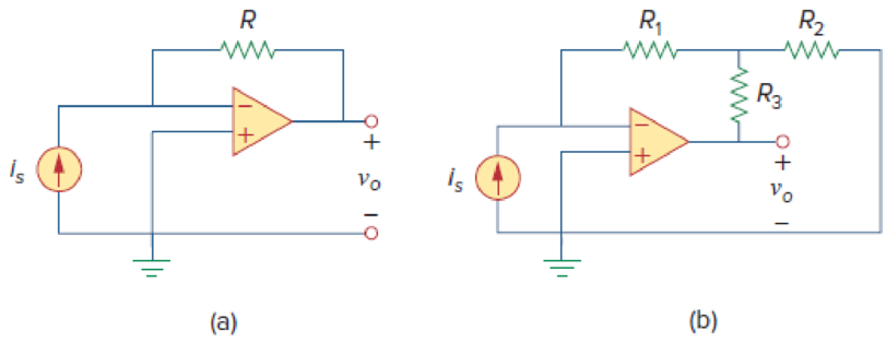
Figure 5.15
For Practice Prob. 5.4.
Want to see the full answer?
Check out a sample textbook solution
Chapter 5 Solutions
Fundamentals of Electric Circuits


- For the circuit configuration below with R1 =6Ω, R2 =5Ω,R3 =4Ω, R4 =7Ω, R5 =15Ω, R6 =16Ω, vg=27V, with ideal op-amps, calculate v0.arrow_forwardAn op-amp with an open-loop gain of 6x10⁵ and Vcc = 15 V has an output voltage of 3 Volts. If the inverting-input voltage is -1.8 microVolts then determine the non-inverting input voltage in microVolts to the single digit decimal place. Do not enter units. For example, if you calculate 3.1x10⁻⁶ Volts as your answer then enter 3.1. Similarly, if you calculate 1.872 x10⁻⁵ Volts as your answer then enter 18.7 (since this is 18.7 microvolts).arrow_forward5.37 Determine the output of the summing amplifier in Fig 5.74arrow_forward
- An op-amp with an open-loop gain of 3x10⁶ and Vcc = 12 V has an inverting-input voltage of 6.7 microVolts and a non-inverting input voltage of 5.4 microVolts. What is its output voltage? Be sure to round your answer to the nearest single digital decimal place. Do not enter units. As an example, if you calculate 7.39 Volts then enter 7.4 as your submitted answerarrow_forwardKindly create a circuit with amplifier with DC power supply and with a gain of 150 with a closed circuit. Kindly provide explanation on how it operates thankyouarrow_forwardAssume that the op amp in the circuit shown is ideal. 1. Calculate vo for the following values of vs: 0.4, 2.0, 3.5, −0.6, −1.6, and −2.4 V. 2. Specify the range of vs required to avoid amplifier saturation.arrow_forward
- In the ideal operational amplifier circuit given in Figure 5, a) Find the voltage V0. B) Find the current I0. Y=3arrow_forwardDesign a three ip amp instrumentation amplifier having gain 20.arrow_forwardThe two input terminals of an op amp are connected to voltage signals of strength 745 micro volts and 740 micro volts respectively.the gain of op amp in common mode is 50*10 power 5 and CMRR is 80dB.calculate the output voltage and percentage error due to common modearrow_forward
- Figure 1(a) shows a voltage subtraction amplifier where its inputs, VO1 and VO2 are from the circuit of Figure 1(b) and Figure 1(c) respectively. Determine the output voltage, VO, given that Rf = 20 kΩ, R1 = 10 kΩ, R2 = 5 kΩ and R3 = 2.5 kΩ whereby inputs, Vi1 = 4m sin (1000t)V and Vi2 =10m sin (1000t)V. 1. Refer Figure 1(c), calculate output for the op-amp 1: V1 = m sin 1000t 2. Refer Figure 1(c), calculate output for the op-amp 2: V2 = m sin 1000t 3. Refer Figure 1(c), calculate output for the op-amp 3: V3= m sin 1000t 4. Refer Figure 1(b), calculate Vo2 : Vo2 = m sin 1000t 5. Refer Figure 1(a), calculate Vo : Vo = m sin 1000tarrow_forwardThe resistor Rf in the circuit attached is adjusted until the ideal op amp saturates. Specify Rf in kilo-ohms.arrow_forwardFor the circuit, assuming an ideal op amp, and given Vs = - 1.5 V, R1 = 1 K ohm, R2 = 15k ohm, and R3 = 5k ohm, answer the following question. (Annotate diagram to show branches and nodes.) (a) Find the currents in all the branches (b) Find the voltages at all nodes (c) Find the power dissipated in each resistor (a) Find the total power dissipated in all resistors (e) How much power is delivered by Vs? (f) Explain: where does the rest of the power come from?arrow_forward
 Introductory Circuit Analysis (13th Edition)Electrical EngineeringISBN:9780133923605Author:Robert L. BoylestadPublisher:PEARSON
 Delmar's Standard Textbook Of ElectricityElectrical EngineeringISBN:9781337900348Author:Stephen L. HermanPublisher:Cengage Learning
 Programmable Logic ControllersElectrical EngineeringISBN:9780073373843Author:Frank D. PetruzellaPublisher:McGraw-Hill Education
 Fundamentals of Electric CircuitsElectrical EngineeringISBN:9780078028229Author:Charles K Alexander, Matthew SadikuPublisher:McGraw-Hill Education
 Electric Circuits. (11th Edition)Electrical EngineeringISBN:9780134746968Author:James W. Nilsson, Susan RiedelPublisher:PEARSON
 Engineering ElectromagneticsElectrical EngineeringISBN:9780078028151Author:Hayt, William H. (william Hart), Jr, BUCK, John A.Publisher:Mcgraw-hill Education,