
Concept explainers
Videos
Design a circuit to amplify the difference between two inputs by 2.5.
- (a) Use only one op amp.
- (b) Use two op amps.
(a)
Design an amplifier circuit that contains only one op amp to amplify the required difference between two inputs.
Explanation of Solution
Calculation:
The difference amplifier is drawn and it is shown in Figure 1.
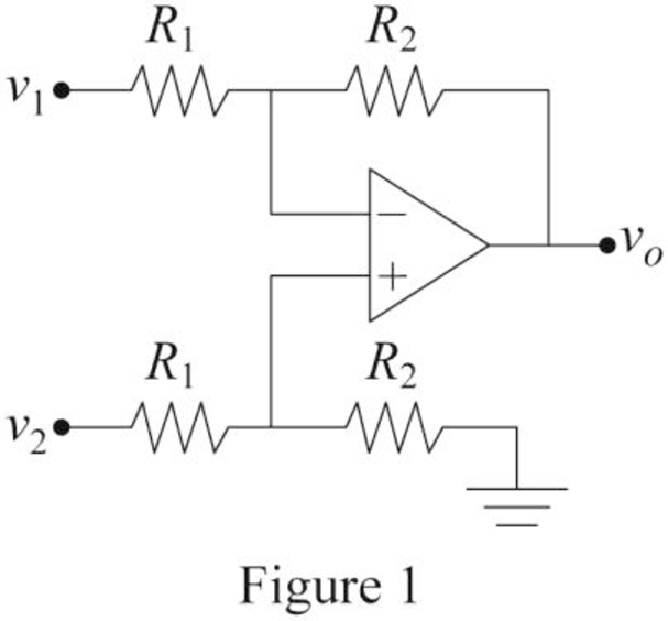
Write the expression for the output voltage
Consider that the required value of difference is 2.5.
Consider the expression for the output voltage of the difference amplifier with the difference of 2.5 between two inputs.
Compare Equations (1) and (2).
Choose the value of resistor
Substitute
Conclusion:
Thus, the required op amp circuit is designed and obtained values are
(b)
Design an amplifier circuit that contains two op amps to amplify the required difference between two inputs.
Explanation of Solution
Calculation:
Consider that the required value of difference is 2.5. To design the required circuit by cascading the inverting amplifier with summer amplifier.
The required difference amplifier with two op amps is drawn and it is shown in Figure 2.
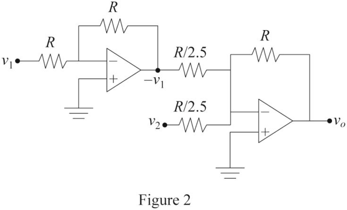
The output voltage of an inverting amplifier is,
Write the expression for the output voltage
Modify Equation (4).
Hence, Equation (4) satisfies the Equation (2).
Re-arrange Equation (4).
Here,
And
Choose the value of resistor R.
Substitute
Substitute
Substitute
Therefore, the value of resistors
Conclusion:
Thus, the required op amp circuit is designed and obtained values are
Want to see more full solutions like this?
Chapter 5 Solutions
Fundamentals of Electric Circuits


- In the op-amp circuit shown below, find V0. 30 kQ Select one: O avo=6V O b.vo=3v c. None of the above ) d.VO=9Varrow_forwardSketch the circuit of summing amplifier using op amp to get Vout= 2V1+ 3V2+5V3.arrow_forwardAn inverting op amp has Rf= 500kohm and R1= 5kohm. Determine the op amp circuit voltage gain, input resistance and output resistance. Also Determine the output voltage and input current if the input voltage is 0.1 V. Assume op amp to be ideal one.arrow_forward
- 3. Consider the op-amp circuit below. Given the input voltage V1= 0.2V, calculate the output voltages V2 and V3.arrow_forwardThe op amp in the circuit shown is ideal. Suppose va=2 V. What value of Rf will cause the op amp to saturate?arrow_forwardBased on the op amp circuit in Figure, answer the following questions,assuming an ideal op-amp. Given:V1 = 1 VI2 = 2 mAV3 = 0.5 VRa = 2 kΩRb = 1 kΩRc = 5 kΩRd = 10 kΩVx = 4VIb = 3.5mANow I need to determine Vo and the current and power through Rd.Please help, Thank youarrow_forward
- The two input terminals of an op amp are connected to voltage signals of strength 745 micro volts and 740 micro volts respectively.the gain of op amp in common mode is 50*10 power 5 and CMRR is 80dB.calculate the output voltage and percentage error due to common modearrow_forwardAssume that Op amp shown is ideal. Given that R1 is 24 Ohm, R2 is 75 Ohm, R3 is 12 Ohm, R4 is 187.5 Ohm. Calculate Vo (Volts).arrow_forwardHi please calculate for the CMRR (measured) with resistor values: R1 = 995 Ohms R2 = 100.8 kOhms R3 = 1003 Ohms R4 = 99.7 kOhms Assume that the op amp itself has infinite CMRR. I will upvote thanks!arrow_forward
- Based on the op amp circuit in Figure, answer the following questions,assuming an ideal op-amp. Given:V1 = 1 VI2 = 2 mAV3 = 0.5 VRa = 2 kΩRb = 1 kΩRc = 5 kΩRd = 10 kΩ Determine the voltage Vx, and the current Ib through Rbarrow_forwardCalculate the output voltage of an op-amp summing amplifier for the given values of voltages and resistors. Use Rf = 1 MΩ. V1 = 5.84V V2 = 8.47V V3 = 8.25V R1 = 482kΩ R2 = 0.58MΩ R3 = 1.31MΩ QUICKLYarrow_forwardThe op amp shown below has a maximum output voltage range from −5 to +5 V. The maximum output current magnitude of the op amp is 20 mA. The slew-rate limit is 5 V/μs. a. Find the full-power bandwidth of the op amparrow_forward
 Delmar's Standard Textbook Of ElectricityElectrical EngineeringISBN:9781337900348Author:Stephen L. HermanPublisher:Cengage Learning