
Concept explainers
Videos
(a)
To determine the maximum height that the water will reach in the tank.
Explanation of Solution
The diameter of the tank is
The following figure shows the schematic diagram of water tank system.
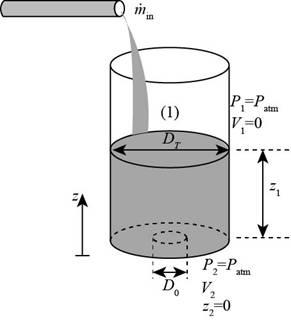
Figure-(1)
Write the expression for Bernoulli theorem between the point
Here, the pressure at point
Substitute
Write the expression for the mass flow rate at the point
Here, the area of the orifice is
Write the expression for the area of the orifice.
Here, the diameter of the orifice is
Substitute
Square on both sides in Equation (IV).
Substitute
Substitute
The maximum height reached by the water of the tank is
(b)
The relation between water height as a function of time.
Explanation of Solution
Write the expression for the principle of conservation of mass for the control volume undergoing a change during period
Here, the mass flow rate of orifice is
Write the expression for the mass flow rate of control volume.
Substitute
Substitute
Write the general expression for
Differentiate Equation (X).
Substitute
Write the expression for the dissolve of fraction.
Dissolve the fraction in Equation (X).
Equate the coefficients of
Substitute
Substitute
Substitute
Integrate Equation (XII) on both sides.
Substitute
Substitute
The relation between the time and the height is
Want to see more full solutions like this?
Chapter 5 Solutions
FLUID MECHANICS:FUND.+APPL.(LL)>CUSTOM<


- Water enters a hydraulic turbine through a 30-cm-diameter pipe at a rate of 0.6 m3/s and exits through a 25-cm-diameter pipe. The pressure drop in the turbine is measured by a mercury manometer to be 1.2 m. For a combined turbine– generator efficiency of 83 percent, determine the net electric power output. Disregard the effect of the kinetic energy correction factorsarrow_forwarda cylindrical tank 90 cm high and 60 cm in diameter, open to the atmosphere, initially completely with water it is filled. Then, the drain plug located at the bottom edge of the tank is pulled out, so that the water it starts to empty from the tank in the form of a water jet with a diameter of 1.35 cm. The average of the water jet from the tank the output speed does not change approximately according to the correlation V=(2gh)1/2. Here in h tabk the height of the water from the center of the hole is the gravitational acceleration g. The level of water in the tank determine the time it will take to fall to a height of 60 cm from the basearrow_forwardA pressurized tank of water has a 10-cm-diameter orifice at the bottom, where water discharges to the atmosphere. The water level is 2.5 m above the outlet. The tank air pressure above the water level is 250 kPa (absolute) while the atmospheric pressure is 100 kPa. Neglecting frictional effects, determine the initial discharge rate of water from the tank.arrow_forward
- A 3-m-high large tank is initially filled with water. The tank water surface is open to the atmosphere, and a sharp-edged 10-cm-diameter orifice at the bottom drains to the atmosphere through a horizontal 80-m-long pipe. The total irreversible head loss of the system is determined to be 1.5 m. Disregard the effect of the kinetic energy correction factors. Using appropriate software, investigate the effect of the tank height on the initial discharge velocity of water from the completely filled tank. Let the tank height vary from 2 to 15 m in increments of 1 m, and assume the irreversible head loss to remain constant. Tabulate and plot the results.arrow_forwardInclude a free body diagram. Water is being pumped from a large lake to a reservoir 25 m above at a rate of 25 L/s by a 10-kW (shaft) pump. If the irreversible head loss of the piping system is 5 m, determine the mechanical efficiency of the pump. prove the answer: 73.6 percentarrow_forwardWater flows in a 15-cm-diameter pipe at a velocity of 1.8 m/s. If the head loss along the pipe is estimated to be 16 m, the required pumping power to overcome this head loss is (a) 3.22 kW (b) 3.77 kW (c) 4.45 kW (d) 4.99 kW (e) 5.54 kWarrow_forward
- Water flows at a rate of 0.040 m3/s in a horizontal pipe whose diameter is reduced from 15 cm to 8 cm by a reducer. If the pressure at the centerline is measured to be 480 kPa and 440 kPa before and after the reducer, respectively, determine the irreversible head loss in the reducer. Take the kinetic energy correction factors to be 1.05.arrow_forwardWater enters a tank of diameter DT steadily at a mass flow rate of min. An orifice at the bottom with diameter Do allows water to escape. The orifice has a rounded entrance, so the frictional losses are negligible. If the tank is initially empty, (a) determine the maximum height that the water will reach in the tank and (b) obtain a relation for water height z as a function of time?arrow_forwardA pump draws 20 kW of electrical power while pumping oil with a density of 780 kg/m^3 at a flow rate of 0.3 m^3/s. The diameters of the inlet and outlet pipes of the pump are 7 cm and 12 cm, respectively. Since the pressure increase in the pump is 220 kPa and the motor efficiency is 91%, determine the mechanical efficiency of the pump. (Ignore the kinetic energy correction factor, α=1, Ignore the height differences inside the pump, the head loss in the pump hL=0.5)arrow_forward
- Water enters a tank of diameter DT steadily at a mass flow rate of m . in. An orifice at the bottom with diameter Do allows water to escape. The orifice has a rounded entrance, so the frictional losses are negligible. If the tank is initially empty, (a) determine the maximum height that the water will reach in the tank and (b) obtain a relation for water height z as a function of time.arrow_forwardWater flows in a 15-cm-diameter pipe at a velocity of 1.8 m/s. If the head loss along the pipe is estimated to be 19 m, the required pumping power (in kW) to overcome this head loss is ?"arrow_forwardThe impeller of a centrifugal blower has a radius of 18 cm and a blade width of 6.1 cm at the inlet, and a radius of 30 cm and a blade width of 3.4 cm at the outlet. The blower delivers atmospheric air at 20°C and 95 kPa. Disregarding any losses and assuming the tangential components of air velocity at the inlet and the outlet to be equal to the impeller velocity at respective locations, determine the volumetric flow rate of air when the rotational speed of the shaft is 900 rpm and the power consumption of the blower is 120 W. Also determine the normal components of velocity at the inlet and outlet of the impeller.arrow_forward
 Principles of Heat Transfer (Activate Learning wi...Mechanical EngineeringISBN:9781305387102Author:Kreith, Frank; Manglik, Raj M.Publisher:Cengage Learning