EBK INTRODUCTORY CIRCUIT ANALYSIS
13th Edition
ISBN: 8220100668234
Author: Boylestad
Publisher: PEARSON
expand_more
expand_more
format_list_bulleted
Concept explainers
Videos
Textbook Question
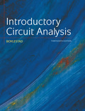
Chapter 5, Problem 4P
Find the total resistance
Expert Solution & Answer
Want to see the full answer?
Check out a sample textbook solution
Students have asked these similar questions
Include an illustration of the circuit in the solutions. Thank you
Compute the total resistance.
1) In the Fig. 5 – 4, between points A and B, which branch of the circuit has the greatest current flow if all resistors have the exact values indicated?a. R2, R3.b. R4c. R5d. All branch currents are the same value.
2) Which of the following would be a true statement if resistor R7 became short circuited in Fig. 5 – 4.a. Current flow would decrease.b. Voltage E AB would decrease.c. Voltage E CD would increase.d. Current flow would increase.
6. Which of the following would be a false statement if resistor R7 opened in Fig. 5 – 4?a. Current flow would decrease.b. Voltage E AB would decrease.c. Voltage E CD would increase.d. None of the above.
Chapter 5 Solutions
EBK INTRODUCTORY CIRCUIT ANALYSIS
Ch. 5 - For each configuration in Fig. 5.88, find the...Ch. 5 - For each configuration in Fig. 5.89, find the...Ch. 5 - Find the total resistance RT for each...Ch. 5 - Find the total resistance RT for each...Ch. 5 - For each circuit board in Fig. 5.92, �nd the...Ch. 5 - For the circuit in Fig. 5.93, composed of standard...Ch. 5 - For each configuration in Fig. 5.94, determine the...Ch. 5 - Find the resistance R, given the ohmmeter reading...Ch. 5 - What is the ohmmeter reading for each...Ch. 5 - For the series configuration in Fig. 5.97,...
Ch. 5 - For the series configuration in Fig. 5.98,...Ch. 5 - Find the applied voltage necessary to develop the...Ch. 5 - For each network in Fig. 5.100, constructed of...Ch. 5 - For each configuration in Fig. 5.101, what are the...Ch. 5 - For each configuration of Fig. 5.102, find the...Ch. 5 - For the circuit in Fig. 5.103, constructed of...Ch. 5 - Find the unknown quantities for the circuit of...Ch. 5 - Find the unknown quantities for the circuit in...Ch. 5 - Eight holiday lights are connected in series as...Ch. 5 - For the conditions specified in Fig. 5.107,...Ch. 5 - Combine the series voltage sources in Fig. 5.108,...Ch. 5 - Determine the current I and its direction for each...Ch. 5 - Find {he unknown voltage source and resistor for...Ch. 5 - Using Kirchhoffs voltage law, find the unknown...Ch. 5 - Find the current I for the network of Fig. 5.112....Ch. 5 - Using Kirchhoffs voltage law, determine the...Ch. 5 - Using Kirchhoffs voltage law, find the unknown...Ch. 5 - Determine the values of the unknown resistors in...Ch. 5 - For the configuration in Fig. 5.116, with standard...Ch. 5 - Using the voltage divider rule, find the indicated...Ch. 5 - Using the voltage divider rule or Kirchhoffs...Ch. 5 - Using the voltage divider rule or Kirchhoffs...Ch. 5 - Using the information provided, find the unknown...Ch. 5 - Using the voltage divider rule, �nd the unknown...Ch. 5 - Design a voltage divider circuit that will permit...Ch. 5 - Design the voltage divider in Fig. 5.122 such that...Ch. 5 - Find the voltage across each resistor in Fig....Ch. 5 - Design the circuit in Fig. 5.124 such that...Ch. 5 - Determine the voltages Va,Vb, and Vab for the...Ch. 5 - Determine the current I (with direction) and the...Ch. 5 - For the network in Fig. 5.127 determine the...Ch. 5 - Given the information appearing in Fig. 5.128,...Ch. 5 - Determine the values of R1,R2,R3, and R4 for the...Ch. 5 - For the network in Fig. 5.130, determine the...Ch. 5 - For the integrated circuit in Fig. 5.131,...Ch. 5 - For the integrated circuit in Fig. 5.132,...Ch. 5 - Find the internal resistance of a battery that has...Ch. 5 - Find the voltage to the load (full-and conditions)...Ch. 5 - Determine the current through the circuit in Fig....Ch. 5 - Use the computer to verify the results of Example...Ch. 5 - Use the computer to verify the results of Example...Ch. 5 - Use the computer to verify the results of Example...
Additional Engineering Textbook Solutions
Find more solutions based on key concepts
Three point charges of equal magnitude q, that will yield a zero net electric field at the origin.
Engineering Electromagnetics
Find I0 and I1 in the circuit in Fig.P2.12.
Basic Engineering Circuit Analysis
Assume a telephone signal travels through a cable at two-thirds the speed of light. How long does it take the s...
Electric Circuits (10th Edition)
What is the color code for a 365- five-band precision resistor with a tolerance of 5 percent?
ELECTRICITY FOR TRADES (LOOSELEAF)
Does the severity of an electric shock increase ordecrease with eh of the following changes? a. A decrease in t...
Electric Motors and Control Systems
When travelers from the USA and Canada visit Europe, they encounter a different power distribution system. Wall...
Electric machinery fundamentals
Knowledge Booster


Learn more about
Need a deep-dive on the concept behind this application? Look no further. Learn more about this topic, electrical-engineering and related others by exploring similar questions and additional content below.Similar questions
- The variable resistor in the circuit attached is adjusted for maximum power transfer to R0. a) find the value of R0. b) find the maximum power that can be delivered to R0.arrow_forwardThe diagram shows the circuit used to investigate how the current varies with potential difference for an electrical component P. The circuit contains an ammeter and a voltmeter. P (1)On the diagram. label the ammgter A and the voltmeter Volteter connectel aceross te inal, Ammeter Connected in sertes to the cirevil. (ii) The position of the contact of the potential divider is moved so that the reading on the voltmeter becomes zero. Label this position Z.arrow_forwardContext: The results shown in table 5.0 were obtained using a potentiometer on a breadboard and measured with a DMM multimeter using the Ohmmeter function. Please answer the question below including as much detail and information as possible. Thank you very much.arrow_forward
- Choose Values Of Resistance (Rc And Rs) In Kilo Ohm And Then Voltage Sources In Volt (Vcc > Ves). Find All Currents And All Voltages Rc RB VCE VCC VBBarrow_forwardQ5. Two same size PV Modules are connected in Parallel. The specification of each module is given as, Number of cells = 39, Area of each cell is 10 cm x 10 cm, the insolation value is 900 W/m?, take efficiency of module as 12%. Calculate the following for the above PV Panel. A. Total Output Voltage B. Total Current Output D. Total Power Outputarrow_forwardProblem 5.1: Calculate the voltage at V relative to ground in the following circuit. Assume the following values: V1 = 12 V, V2 = 10 V, R₁ =4 kQ, R2 = 2 kQ, and R3 = 3 kQ,. Give your answer in units of volts. V2 R₁ V +1 V₁ Ry w R2arrow_forward
- 5.) When a resistance of 3 ohms is placed across the terminals of battery, the current is 2A. When the resistance is increased to 42 ohms, the current falls to 1 A. Find emf of battery and its internal resistance.arrow_forwardThe circuits branch is defined as: Select one: a. a single path in a network, composed of two parallel elements and the node at each end of that element. b. a single path in a network, composed of one simple element and the node at each end of that element. C. a single path in a network, composed of one source and parallel resistor and a node at each end of the elements. d. None of the above.arrow_forwardCalculate the equivalent resistance Rab in the given circuit.arrow_forward
- In figure 5.1 of Experiment # 5, what is the computed value of VTH? Show the complete solution. 752 1502 A 5V 2202 4702 B VTH = Blank 1 V (type your answer with 2 decimal places) (+arrow_forwardConsider Two same size PV Modules which are connected in Parallel. The specification of each module is given as: Number of cells = 36, Area of each cell is 12 cm x 12 cm. (Assume the necessary data) Choose from the following the correct statement. a. The output voltage of this panel is 18 V, the output power is 155W b. The output voltage is this panel 18V, the output power is 75W c. The output voltage is this panel 36 V, the output power is 155W d. The output voltage is this panel 36 V, the output power is 75Warrow_forward4) Calculate the value of the multiplier resistance value in multiple range de voltmeter circuit shown in the figure below if Ifse = 50µA and Rm= 1lk. [Ans. 59kN, 140kN, 400kN] H 3V 10V 30Varrow_forward
arrow_back_ios
SEE MORE QUESTIONS
arrow_forward_ios
Recommended textbooks for you
 Introductory Circuit Analysis (13th Edition)Electrical EngineeringISBN:9780133923605Author:Robert L. BoylestadPublisher:PEARSON
 Delmar's Standard Textbook Of ElectricityElectrical EngineeringISBN:9781337900348Author:Stephen L. HermanPublisher:Cengage Learning
 Programmable Logic ControllersElectrical EngineeringISBN:9780073373843Author:Frank D. PetruzellaPublisher:McGraw-Hill Education
 Fundamentals of Electric CircuitsElectrical EngineeringISBN:9780078028229Author:Charles K Alexander, Matthew SadikuPublisher:McGraw-Hill Education
 Electric Circuits. (11th Edition)Electrical EngineeringISBN:9780134746968Author:James W. Nilsson, Susan RiedelPublisher:PEARSON
 Engineering ElectromagneticsElectrical EngineeringISBN:9780078028151Author:Hayt, William H. (william Hart), Jr, BUCK, John A.Publisher:Mcgraw-hill Education,
Introductory Circuit Analysis (13th Edition)
Electrical Engineering
ISBN:9780133923605
Author:Robert L. Boylestad
Publisher:PEARSON
Delmar's Standard Textbook Of Electricity
Electrical Engineering
ISBN:9781337900348
Author:Stephen L. Herman
Publisher:Cengage Learning
Programmable Logic Controllers
Electrical Engineering
ISBN:9780073373843
Author:Frank D. Petruzella
Publisher:McGraw-Hill Education
Fundamentals of Electric Circuits
Electrical Engineering
ISBN:9780078028229
Author:Charles K Alexander, Matthew Sadiku
Publisher:McGraw-Hill Education
Electric Circuits. (11th Edition)
Electrical Engineering
ISBN:9780134746968
Author:James W. Nilsson, Susan Riedel
Publisher:PEARSON
Engineering Electromagnetics
Electrical Engineering
ISBN:9780078028151
Author:Hayt, William H. (william Hart), Jr, BUCK, John A.
Publisher:Mcgraw-hill Education,
Current Divider Rule; Author: Neso Academy;https://www.youtube.com/watch?v=hRU1mKWUehY;License: Standard YouTube License, CC-BY