
Videos
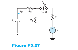
Assume that steady-state conditions exist in the circuit shown in Figure P5.27 for
Want to see the full answer?
Check out a sample textbook solution
Chapter 5 Solutions
Principles And Applications Of Electrical Engineering


- The Thévenin equivalent of a two-terminal network is shown in Figure P5.93. The frequency is f=60 Hz. We wish to connect a load across terminals that consists of a resistance and a capacitance in series such that the power delivered to the resistance is maximized. Find the value of the resistance and the value of the capacitance. Repeat Problem P5.93 with the load required to consist of a resistance and a capacitance in parallel.arrow_forwardAssume that S1 and S2 close at t = 0 in FigureP5.41.a. Find the capacitor voltage vC(t) at t = 0+. b. Find the time constant τ for t ≥ 0.c. Find an expression for vC(t), and sketch thefunction.d. Find vC(t) for each of the following values of t:0, τ, 2τ, 5τ, 10τ .arrow_forwardThe equation of the charge on the capacitor at any time t for an LRC series circuits is givenas a) Assume there is no initial charge and current, sketch the graph of the charge. b) What happen to the charge after a long time? c) State the transient and the steady state terms.arrow_forward
- A lossy capacitor Cx, rated for operation of 5 kV, 50 Hz is represented by an equivalent circuit with an ideal capacitor Cp in parallel with a resistor Rp. Cp is 0.102 microF and Rp=1.25 Mohm. The power loss, and loss tangent of this lossy capacitor at rated voltage respectively ?arrow_forwardDraw the Thévenin and Norton equivalent circuits for Figure P5.91, labeling the elements and terminals.arrow_forwardDescribe the steady-state similarities and differences of DC and AC circuits with purelyresistive elementsarrow_forward
- A resistor, an inductor, and a capacitor are connected in parallel to an ac source with voltage amplitude V and angular frequency v. Let the source voltage be given by v = Vcosvt. (a) Show that each of the instantaneous voltages vR, vL, and vC at any instant is equal to v and that i = iR + iL + iC, where i is the current through the source and iR, iL, and iC are the currents through the resistor, inductor, and capacitor, respectively. (b) What are the phases of iR, iL, and iC with respect to v? Use current phasors to represent i, iR, iL, and iC. In a phasor diagram, show the phases of these four currents with respect to v. (c) Use the phasor diagram of part (b) to show that the current amplitude I for the current i through the source is I = √(I2R) + (IC - IL)2 . (d) Show that the result of part (c) can be written as I = V/Z, with 1/Z = √ (1/R2) + [ωC - (1/ωL)]2.arrow_forwardA resistor (5 Ω) and capacitor (0.05 F) are joined in series with an electromotive force E(t) = 30 −t V. If there is nocharge on the capacitor at time t = 0, find the ensuing charge on the capacitor at time t. The following lineardifferential equation models the charge on the capacitor, q(t). (check the image) How do I go about solving this?arrow_forwardExplain why we replace capacitances with open circuits and inductances with short circuits in dc steady-state analysis.arrow_forward
- Which of the following is true regarding the behavior of capacitors when energized by a DC source? a. At transient state, the capacitor behaves as an open circuit. b. At transient state, the capacitor behaves as a short circuit. c. At steady-state, the capacitor behaves as a short circuit. d. At steady-state, the capacitor behaves as an open circuit.arrow_forwardConsider the circuit shown in the figure, with ε=36.0V, R0=50.0Ω, R=150Ω and L=4.00H. (a) Switch S1 is closed. Just after S1 is closed, what are the current i0 through R0 andthe potential differences VAC and VCB? (b) After S1 has been closed a long time so that the current has reached its final, steady value, what are i0 , VAC and VCB? (c) Find the expressions for i0, VAC and VCB as functions of time since S1 was closed. Do your results agree with what you get in (a) and (b)? Graph i0, VAC and VCB as afunction of time.arrow_forwardCapacitance= 5uF1) Determine the time constant of the circuit for the capacities2) For the capacity value, calculate the estimated time to come to the final state.3) Plot capacitor current and voltage graphs and show if it works in harmony with the time constant you calculated. NOTE: if you want you can use falstad online circuit simulator.arrow_forward
 Introductory Circuit Analysis (13th Edition)Electrical EngineeringISBN:9780133923605Author:Robert L. BoylestadPublisher:PEARSON
 Delmar's Standard Textbook Of ElectricityElectrical EngineeringISBN:9781337900348Author:Stephen L. HermanPublisher:Cengage Learning
 Programmable Logic ControllersElectrical EngineeringISBN:9780073373843Author:Frank D. PetruzellaPublisher:McGraw-Hill Education
 Fundamentals of Electric CircuitsElectrical EngineeringISBN:9780078028229Author:Charles K Alexander, Matthew SadikuPublisher:McGraw-Hill Education
 Electric Circuits. (11th Edition)Electrical EngineeringISBN:9780134746968Author:James W. Nilsson, Susan RiedelPublisher:PEARSON
 Engineering ElectromagneticsElectrical EngineeringISBN:9780078028151Author:Hayt, William H. (william Hart), Jr, BUCK, John A.Publisher:Mcgraw-hill Education,