
Principles And Applications Of Electrical Engineering
6th Edition
ISBN: 9789814577410
Author: RIZZONI
Publisher: Mcgraw-Hill
expand_more
expand_more
format_list_bulleted
Videos
Textbook Question
Chapter 5, Problem 5.80HP
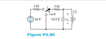
Assume the circuit in Figure P5.80 is in DC steady slate at
Expert Solution & Answer
Want to see the full answer?
Check out a sample textbook solution
Students have asked these similar questions
Assume ?? ≈ 0. Solve this problem using both the exponentialmodel and the constant-voltage model. For the constant-voltage model, use ???,?? = 0.7?
Explaion the concept of RL Circuits in relation with Linear Equation?
5)This MCQ QUESTION FROM BASIC POWER ELECTRICAL ENGINEERING course.
Chapter 5 Solutions
Principles And Applications Of Electrical Engineering
Ch. 5 - Write the differential equations fort t0 for iL...Ch. 5 - Write the differential equation fort t0 for vc in...Ch. 5 - Write the differential equation fort t0 for iC in...Ch. 5 - Write the differential equation for t0 for iL in...Ch. 5 - Write the differential equation for t0 for vc in...Ch. 5 - Write the differential equations for t0 for iC and...Ch. 5 - Prob. 5.7HPCh. 5 - Write the differential equation for t0 for iC in...Ch. 5 - Write the differential equation for t0 for iL in...Ch. 5 - Write the differential equations for: t0 for iL...
Ch. 5 - Determine the initial and final conditions on iL...Ch. 5 - Determine the initial and final conditions on vc...Ch. 5 - Determine the initial and final conditions on iC...Ch. 5 - Determine the initial and final conditions on iL...Ch. 5 - Determine the initial and final conditions on vc...Ch. 5 - Determine the initial and final conditions on iC...Ch. 5 - Determine the initial and final conditions on vC...Ch. 5 - Prob. 5.18HPCh. 5 - Prob. 5.19HPCh. 5 - Determine the initial and final conditions on iL...Ch. 5 - At t=0 , just before the switch is opened, the...Ch. 5 - Prob. 5.22HPCh. 5 - Determine the current ic through the capacitor...Ch. 5 - Prob. 5.24HPCh. 5 - Prob. 5.25HPCh. 5 - Assume that steady-state conditions exist in...Ch. 5 - Assume that steady-state conditions exist in the...Ch. 5 - Prob. 5.28HPCh. 5 - Assume that steady-state conditions exist in the...Ch. 5 - Find the Thévenin equivalent network seen by the...Ch. 5 - Prob. 5.31HPCh. 5 - Prob. 5.32HPCh. 5 - Prob. 5.33HPCh. 5 - For t0 , the circuit shown in Figure P5.34 is at...Ch. 5 - The circuit in Figure P5.35 is a simple model of...Ch. 5 - Prob. 5.36HPCh. 5 - Determine the current iC through the capacitor in...Ch. 5 - Determine the voltage vL across the inductor in...Ch. 5 - Prob. 5.39HPCh. 5 - For t0 , the circuit shown in Figure P5.39 is at...Ch. 5 - Prob. 5.41HPCh. 5 - Prob. 5.42HPCh. 5 - Prob. 5.43HPCh. 5 - Prob. 5.44HPCh. 5 - For the circuit shown in Figure P5.41, assume that...Ch. 5 - Prob. 5.46HPCh. 5 - Prob. 5.47HPCh. 5 - For the circuit in Figure P5.47, assume...Ch. 5 - In the circuit in Figure P5.49, how long after the...Ch. 5 - Refer to Figure P5.49 and assume that the switch...Ch. 5 - The circuit in Figure P5.51 includes a...Ch. 5 - At t=0 the switch in the circuit in Figure...Ch. 5 - Prob. 5.53HPCh. 5 - The analogy between electrical and thermal systems...Ch. 5 - The burner and pot of Problem 5.54 can be modeled...Ch. 5 - Prob. 5.56HPCh. 5 - Prob. 5.57HPCh. 5 - Prob. 5.58HPCh. 5 - The circuit in Figure P5.59 models the charging...Ch. 5 - Prob. 5.60HPCh. 5 - In the circuit shown in Figure P5.61:...Ch. 5 - Prob. 5.62HPCh. 5 - If the switch shown in Figure P5.63 is closed at...Ch. 5 - Prob. 5.64HPCh. 5 - Prob. 5.65HPCh. 5 - Prob. 5.66HPCh. 5 - Prob. 5.67HPCh. 5 - Prob. 5.68HPCh. 5 - Assume the switch in the circuit in Figure...Ch. 5 - Prob. 5.70HPCh. 5 - Prob. 5.71HPCh. 5 - Prob. 5.72HPCh. 5 - Prob. 5.73HPCh. 5 - Prob. 5.74HPCh. 5 - Prob. 5.75HPCh. 5 - Prob. 5.76HPCh. 5 - Prob. 5.77HPCh. 5 - Prob. 5.78HPCh. 5 - Prob. 5.79HPCh. 5 - Assume the circuit in Figure P5.80 is in DC steady...Ch. 5 - Prob. 5.81HPCh. 5 - For t0 , determine v in Figure P5.82, assuming DC...
Knowledge Booster


Learn more about
Need a deep-dive on the concept behind this application? Look no further. Learn more about this topic, electrical-engineering and related others by exploring similar questions and additional content below.Similar questions
- Describe belowarrow_forwarda. The current and voltage for a certain circuit element are shown in Figure P5.38(a). Determine the nature and value of the element. b. Repeat for Figure P5.38(b).arrow_forwardPropose Snubber circuits that will take care of dv/dt, di/dt protection and provide Trapped energy recovery and save against the inductive kick from the load?arrow_forward
- Draw the Nyquist plot for the system in the figure below. Using the Nyquist stability criterion, determine the range of K for which the system is stable. Consider both positive and negative values of K.( Need only handwritten solution please otherwise downvote)arrow_forwardcan you help find power dissipation taking die size into account. In the power dissipation formula, where s is the technology factor, can capacitance be thought of as die-size?Or how do die size and power dissipation correlate?arrow_forwardAn 8 μF capacitor is a 200 V DC in series with a 0.5 MΩ resistorlinked to source. According to this;a) τ =?b) Initial value of charging currentc) The time required for the voltage at the capacitor ends to become 160 V.d) 4 s after connecting to the source, i =? and Vc =? Calculate the values.arrow_forward
- Suppose we have a capacitance C discharging through a resistance R. Define and give an expression for the time constant. To attain a long time constant, do we need large or small values for R? For C?arrow_forwardProvide 1 example of miller effect capacitance with its derivations.arrow_forwardExplore the environmental and regulatory considerations in modern power system planning and development.arrow_forward
- Explain the phase difference between pure resistor, pure inductor and pure capacitor circuit in detail in an AC circuit. Note : ( please write details by words)arrow_forwarda) We assume that the switch is on. Calculate the reactance values and find the charging current in the circuit below. Is the circuit capacitive or inductive? Show that the voltage across the capacitance can be slightly larger than the source voltage U. (This is called the Ferranti effect and means that we can get a voltage rise beyond overhead lines with small loads. This is mostly relevant at the highest voltage levels. The frequency f is 50Hz, and assume voltage U= √2⋅24kVarrow_forwardIn U.S. residences, electrical power is generally utilized at a nominal voltage of 120 V rms. What problems would become pronounced if the power distribution system and household appliances had been designed for a lower voltage (say, 12 V rms)? For a higher voltage (say, 12 kV)?arrow_forward
arrow_back_ios
SEE MORE QUESTIONS
arrow_forward_ios
Recommended textbooks for you
 Introductory Circuit Analysis (13th Edition)Electrical EngineeringISBN:9780133923605Author:Robert L. BoylestadPublisher:PEARSON
 Delmar's Standard Textbook Of ElectricityElectrical EngineeringISBN:9781337900348Author:Stephen L. HermanPublisher:Cengage Learning
 Programmable Logic ControllersElectrical EngineeringISBN:9780073373843Author:Frank D. PetruzellaPublisher:McGraw-Hill Education
 Fundamentals of Electric CircuitsElectrical EngineeringISBN:9780078028229Author:Charles K Alexander, Matthew SadikuPublisher:McGraw-Hill Education
 Electric Circuits. (11th Edition)Electrical EngineeringISBN:9780134746968Author:James W. Nilsson, Susan RiedelPublisher:PEARSON
 Engineering ElectromagneticsElectrical EngineeringISBN:9780078028151Author:Hayt, William H. (william Hart), Jr, BUCK, John A.Publisher:Mcgraw-hill Education,
Introductory Circuit Analysis (13th Edition)
Electrical Engineering
ISBN:9780133923605
Author:Robert L. Boylestad
Publisher:PEARSON
Delmar's Standard Textbook Of Electricity
Electrical Engineering
ISBN:9781337900348
Author:Stephen L. Herman
Publisher:Cengage Learning
Programmable Logic Controllers
Electrical Engineering
ISBN:9780073373843
Author:Frank D. Petruzella
Publisher:McGraw-Hill Education
Fundamentals of Electric Circuits
Electrical Engineering
ISBN:9780078028229
Author:Charles K Alexander, Matthew Sadiku
Publisher:McGraw-Hill Education
Electric Circuits. (11th Edition)
Electrical Engineering
ISBN:9780134746968
Author:James W. Nilsson, Susan Riedel
Publisher:PEARSON
Engineering Electromagnetics
Electrical Engineering
ISBN:9780078028151
Author:Hayt, William H. (william Hart), Jr, BUCK, John A.
Publisher:Mcgraw-hill Education,
Lesson 2 - Source Transformations, Part 2 (Engineering Circuits); Author: Math and Science;https://www.youtube.com/watch?v=7gno74RhVGQ;License: Standard Youtube License