
Videos
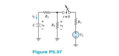
Determine the current
Want to see the full answer?
Check out a sample textbook solution
Chapter 5 Solutions
Principles And Applications Of Electrical Engineering


- a) Find the final value for the capacitor voltage (Vc(∞ ))? b) Find the circuit time constant for t>0? c) Find an expression for the capcitor voltage for t>0?arrow_forwardSolve for the mesh currents shown in Figure P5.54.arrow_forwardDraw the Thévenin and Norton equivalent circuits for Figure P5.91, labeling the elements and terminals.arrow_forward
- The equation of the charge on the capacitor at any time t for an LRC series circuits is givenas a) Assume there is no initial charge and current, sketch the graph of the charge. b) What happen to the charge after a long time? c) State the transient and the steady state terms.arrow_forwardDescribe the steady-state similarities and differences of DC and AC circuits with purelyresistive elementsarrow_forwardSolve for the node voltage shown in Figure P5.54.arrow_forward
- Assume that S1 and S2 close at t = 0 in FigureP5.41.a. Find the capacitor voltage vC(t) at t = 0+. b. Find the time constant τ for t ≥ 0.c. Find an expression for vC(t), and sketch thefunction.d. Find vC(t) for each of the following values of t:0, τ, 2τ, 5τ, 10τ .arrow_forwardA lossy capacitor Cx, rated for operation of 5 kV, 50 Hz is represented by an equivalent circuit with an ideal capacitor Cp in parallel with a resistor Rp. Cp is 0.102 microF and Rp=1.25 Mohm. The power loss, and loss tangent of this lossy capacitor at rated voltage respectively ?arrow_forwardThe Thévenin equivalent of a two-terminal network is shown in Figure P5.93. The frequency is f=60 Hz. We wish to connect a load across terminals that consists of a resistance and a capacitance in series such that the power delivered to the resistance is maximized. Find the value of the resistance and the value of the capacitance. Repeat Problem P5.93 with the load required to consist of a resistance and a capacitance in parallel.arrow_forward
- Which of the following is true regarding the behavior of capacitors when energized by a DC source? a. At transient state, the capacitor behaves as an open circuit. b. At transient state, the capacitor behaves as a short circuit. c. At steady-state, the capacitor behaves as a short circuit. d. At steady-state, the capacitor behaves as an open circuit.arrow_forwardDetermine the power for each source shown in Figure P5.76. Also, state whether each source is delivering or absorbing energy.arrow_forwardExplain why we replace capacitances with open circuits and inductances with short circuits in dc steady-state analysis.arrow_forward
 Introductory Circuit Analysis (13th Edition)Electrical EngineeringISBN:9780133923605Author:Robert L. BoylestadPublisher:PEARSON
 Delmar's Standard Textbook Of ElectricityElectrical EngineeringISBN:9781337900348Author:Stephen L. HermanPublisher:Cengage Learning
 Programmable Logic ControllersElectrical EngineeringISBN:9780073373843Author:Frank D. PetruzellaPublisher:McGraw-Hill Education
 Fundamentals of Electric CircuitsElectrical EngineeringISBN:9780078028229Author:Charles K Alexander, Matthew SadikuPublisher:McGraw-Hill Education
 Electric Circuits. (11th Edition)Electrical EngineeringISBN:9780134746968Author:James W. Nilsson, Susan RiedelPublisher:PEARSON
 Engineering ElectromagneticsElectrical EngineeringISBN:9780078028151Author:Hayt, William H. (william Hart), Jr, BUCK, John A.Publisher:Mcgraw-hill Education,