
Mastering Engineering with Pearson eText -- Standalone Access Card -- for Electrical Engineering: Principles & Applications
7th Edition
ISBN: 9780134486970
Author: Allan R. Hambley
Publisher: PEARSON
expand_more
expand_more
Solutions are available for other sections.
Concept explainers
Videos
Textbook Question
Chapter 5, Problem
Two loads. A and B, are connected in parallel across a 1-kV-rms 60-Hz line, as shown in Figure P5.81. Load A consumes 10 kW with a 90 percent lagging power facto. Load B has an apparent power of 15 ICVA with an 80 percent lagging power factor. Find the power, reactive power, and apparent power delivered by the source. What is the power factor seen by the source?
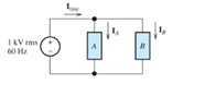
Figure P5.81
Expert Solution & Answer
Want to see the full answer?
Check out a sample textbook solution
Students have asked these similar questions
Two loads, A and B, are connected in parallel across a 1-kV-rms 60-Hz line, as shown in Figure P5.81. Load A consumes 10 kW with a 90 percent lagging power factor. Load B has an apparent power of 15 kVA with an 80 percent lagging power factor. Find the power, reactive power, and apparent power delivered by the source. What is the power factor seen by the source?
P5.16. Two loads, A and B, are connected in parallel across a 1-kV-rms
60-Hz line, as shown in Figure P5.16. Load A consumes 10 kW with
a 90 percent lagging power factor. Load B has an apparent power of
15 kVA with an 80 percent lagging power factor. Find the power, re-
active power, and apparent power delivered by the source. What is the
power factor seen by the source?
Iine
'line
Ig
1 kV rms
o odi ssbin.S
B.
60 Hz
Figure P5.16
*P5.75. Two loads-A and B - are connected in par-
allel across a 1-kV rms 60-Hz line, as shown in
Figure P5.75. Load A consumes 10 kW with a
90-percent-lagging power factor. Load B has
an apparent power of 15 kVA with an 80-
percent-lagging power factor. Find the power,
reactive power, and apparent power deliv-
ered by the source. What is the power factor
seen by the source?
1 kV rms
60 Hz
+
Line
0 0
A
B
Figure P5.75
IB
4
Chapter 5 Solutions
Mastering Engineering with Pearson eText -- Standalone Access Card -- for Electrical Engineering: Principles & Applications
Ch. 5 - Consider the plot of the sinusoidal voltage...Ch. 5 - Repeat Problem P5.3 for v(t) = 50 sin (500t+120) .Ch. 5 - A sinusoidal voltage v(t) has an rms value of 20...Ch. 5 - A current i(t)=10cos(2000t) flows through a 100...Ch. 5 - We have a voltage v(t)=1000sin(500t) across a 500...Ch. 5 - Calculate the rms value of the half-wave rectified...Ch. 5 - We have v1(t)=10cos(t+30) . The current i1(t)has...Ch. 5 - Solve for the mesh currents shown in Figure P5.55.Ch. 5 - Two loads. A and B, are connected in parallel...
Knowledge Booster


Learn more about
Need a deep-dive on the concept behind this application? Look no further. Learn more about this topic, electrical-engineering and related others by exploring similar questions and additional content below.Similar questions
- Let a 100V sinusoidal source be connected to a series combination of a 3 resistor, an 8 inductor, and a 4 capacitor. (a) Draw the circuit diagram. (b) Compute the series impedance. (C) Determine the current I delivered by the source. Is the current lagging or leading the source voltage? What is the power factor of this circuit?arrow_forwardTwo loads, A and B, are connected in parallel across a 1-kV-rms 60-Hz line, as shown in Figure P5.81. Load A consumes 10 kW with a 90 percent lagging power factor. Load B has an apparent power of 15 kVA with an 80 percent lagging power factor. Find the power, reactive power, and apparent power delivered by the source. What is the power factor seen by the source? Repeat Problem P5.81 if load A consumes 5 kW with a 90 percent lagging power factor and load B consumes 10 kW with an 80 percent leading power factor.arrow_forwardDetermine the complex power, power, reactive power, and apparent power absorbed by the load in Figure T5.6. Also, determine the power factor for the load.arrow_forward
- Consider the circuit shown in Figure P5.79. Find the phasor current I. Find the power, reactive power, and apparent power delivered by the source. Find the power factor and state whether it is lagging or leading.arrow_forwardP5.94. A delta-connected source delivers power to a delta-connected load, as shown in Figure P5.94. The rms line-to-line voltage at the source is Vabrms = 440 V. The load impedance is ZA = 12 + j3. Find IaA, VAB, IAB, the total power delivered to the load, and the power lost in the line. a Vm/150 Vm/30° + + с + b 1Ω M 1Ω M Vm/-90° +j2 Ω 0000 +j2 Ω 0000 192 +j2 Ω M 0000 Figure P5.94 B ZA ZA с A ZAarrow_forwardP5.94. A delta-connected source delivers power to a delta-connected load, as shown in Figure P5.94. The rms line-to-line voltage at the source is Vabrms = 440 V. The load impedance is ZA = 12 + j3. Find IaA, VAB,IAB, the total power delivered to the load, and the power lost in the line. 12 +j2 2 Vm 30° 12 +j2 2 ZA a +) В b. ZA Vm -90° Vm /150° 1Ω +j2 Q Figure P5.94 15arrow_forward
- For the system in the figure: Find the total average power, total reactive power, total apparent power, and total power factor. Find the current Is (in phasor form). If the loads can be modeled as a resistance in series with a reactive element (capacitor or inductor), find the impedance of each load. Confirm the result of part B using the input voltage and the result of part C. ..arrow_forwardWhat are the customary units for real power? For reactive power? For apparent power?arrow_forwardFind the power, reactive power, and apparent power delivered by the source in Figure P5.83. Find the power factor and state whether it is leading or lagging. Repeat Problem P5.83 with the resistance, inductance, and capacitance connected in series rather than in parallel.arrow_forward
- Determine the rms value of the current shown in Figure T5.1 and the average power delivered to the 50-Ω resistance.arrow_forward. Determine the capacitance value that, when placed in parallel with this load, would produce a unity power factor. Assume that the source is 230 V at 60 Hz. The Q shown is a positive Inductive reactive power, which would have to be “offset” by the same value of Reactive Capacitance Power.arrow_forwardConsider the situation shown in Figure P5.85. A 1000-V-rms source delivers power to a load. The load consumes 100 kW with a power factor of 25 percent lagging. a. Find the phasor I, assuming that the capacitor is not connected to the circuit. b. Find the value of the capacitance that must be connected in parallel with the load to achieve a power factor of 100 percent. Usually, power-systems engineers rate capacitances used for power-factor correction in terms of their reactive power rating. What is the rating of this capacitance in kVAR? Assuming that this capacitance is connected, find the new value for the phasor I. c. Suppose that the source is connected to the load by a long distance. What are the potential advantages and disadvantages of connecting the capacitance across the load?arrow_forward
arrow_back_ios
SEE MORE QUESTIONS
arrow_forward_ios
Recommended textbooks for you
 Power System Analysis and Design (MindTap Course ...Electrical EngineeringISBN:9781305632134Author:J. Duncan Glover, Thomas Overbye, Mulukutla S. SarmaPublisher:Cengage Learning
Power System Analysis and Design (MindTap Course ...
Electrical Engineering
ISBN:9781305632134
Author:J. Duncan Glover, Thomas Overbye, Mulukutla S. Sarma
Publisher:Cengage Learning
What is the Difference Between Single Phase and Three Phase???; Author: Electrician U;https://www.youtube.com/watch?v=FEydcr4wJw0;License: Standard Youtube License