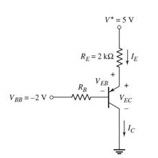
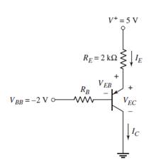
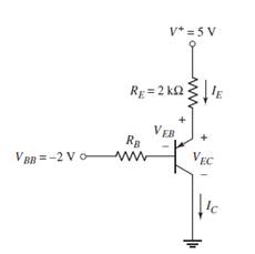
The circuit elements in Figure 5.36(a) are V + = 5 V , V B B = − 2 V , R E = 2 kΩ , and R B = 180 kΩ . Assume V E B (on) = 0.7 V . Plot the Q -point on the load line for (a) β = 40 , (b) β = 60 , (c) β = 100 , and (d) β = 150 . (Ans. (a) I C Q = 0.962 mA , (b) I C Q = 1.25 mA , (c) I C Q = 1.65 mA , (d) I C Q = 1.96 mA )
The circuit elements in Figure 5.36(a) are V + = 5 V , V B B = − 2 V , R E = 2 kΩ , and R B = 180 kΩ . Assume V E B (on) = 0.7 V . Plot the Q -point on the load line for (a) β = 40 , (b) β = 60 , (c) β = 100 , and (d) β = 150 . (Ans. (a) I C Q = 0.962 mA , (b) I C Q = 1.25 mA , (c) I C Q = 1.65 mA , (d) I C Q = 1.96 mA )
The circuit elements in Figure 5.36(a) are
V
+
=
5
V
,
V
B
B
=
−
2
V
,
R
E
=
2
kΩ
, and
R
B
=
180
kΩ
. Assume
V
E
B
(on)
=
0.7
V
. Plot the Q-point on the load line for (a)
β
=
40
, (b)
β
=
60
, (c)
β
=
100
, and (d)
β
=
150
. (Ans. (a)
I
C
Q
=
0.962
mA
, (b)
I
C
Q
=
1.25
mA
, (c)
I
C
Q
=
1.65
mA
, (d)
I
C
Q
=
1.96
mA
)
a.
Expert Solution
To determine
To plot: The Q -point on the load line for the given circuit.
Answer to Problem 5.9EP
The Q-point is at VECQ=3.028 V and ICQ=0.962 mA .
Explanation of Solution
Given Information:
V+=5 V,VBB=−2 V, RE=2 kΩ,RB=180 kΩ , β=40 and VEB(on)=0.7 V
Calculation:
Find the quiescent collector current and identify the load line equation. Then find the quiescent emitter to collector voltage. The figure shows the circuit
Then, draw the load line and mark the Q-point (red)on it as below.
b.
Expert Solution
To determine
To plot: The Q-point on the load line for the given circuit.
Answer to Problem 5.9EP
The Q -point is at VECQ=2.46 V and ICQ=1.25 mA .
Explanation of Solution
Given Information:
V+=5 V,VBB=−2 V, RE=2 kΩ,RB=180 kΩ , β=60 and VEB(on)=0.7 V
Calculation:
Find the quiescent collector current and identify the load line equation. Then find the quiescent emitter to collector voltage. The figure shows the circuit
Then, draw the load line and mark the Q-point (red)on it as below.
c.
Expert Solution
To determine
To plot: The Q -point on the load line for the given circuit.
Answer to Problem 5.9EP
The Q-point is at VECQ=1.67 V and ICQ=1.65 mA .
Explanation of Solution
Given Information:
V+=5 V,VBB=−2 V, RE=2 kΩ,RB=180 kΩ , β=100 and VEB(on)=0.7 V
Calculation:
Find the quiescent collector current and identify the load line equation. Then find the quiescent emitter to collector voltage. The figure shows the circuit
Then we can draw the load line and mark the Q-point (red)on it as below.
d.
Expert Solution
To determine
To plot: TheQ -point on the load line for the given circuit.
Answer to Problem 5.9EP
The Q -point is at VECQ=1.05 V and ICQ=1.96 mA .
Explanation of Solution
Given Information:
V+=5 V,VBB=−2 V, RE=2 kΩ,RB=180 kΩ , β=150 and VEB(on)=0.7 V
Calculation:
Find the quiescent collector current and identify the load line equation. Then find the quiescent emitter to collector voltage. The figure shows the circuit
In your own words, briefly describe the basic operation of an E-MOSFET.
For the transistor , IS = 4 × 10⁻¹⁶ μA,βF = 75, and βR = 4. (a) Label the collector, base,and emitter terminals of the transistor. (b) What isthe transistor type? (c) Label the emitter-base andcollector-base voltages, and label the normal direction for IE , IC, and IB. (d) Write the simplified formof the transport model equations that apply to thisparticular circuit configuration. Write an expressionfor IE /IB. Write an expression for IE /IC. (e) Findthe values of IE , IC, IB, VC B, and VE B.
24. For the given circuit, VCC = 17 volts, RB = 500 KΩ,RC =6KΩ,RE =6KΩandβ=120.Assume Transistor is Silicon, VBE=0.7 volts.
a. Compute for the base current Q-point, IBQ (in Amperes)
b. Compute for the collector current Q-point, ICQ (in Amperes)
c. Compute for the collector-to-emitter voltage, VCEQ (in Volts)
Need a deep-dive on the concept behind this application? Look no further. Learn more about this topic, electrical-engineering and related others by exploring similar questions and additional content below.


 Introductory Circuit Analysis (13th Edition)Electrical EngineeringISBN:9780133923605Author:Robert L. BoylestadPublisher:PEARSON
 Delmar's Standard Textbook Of ElectricityElectrical EngineeringISBN:9781337900348Author:Stephen L. HermanPublisher:Cengage Learning
 Programmable Logic ControllersElectrical EngineeringISBN:9780073373843Author:Frank D. PetruzellaPublisher:McGraw-Hill Education
 Fundamentals of Electric CircuitsElectrical EngineeringISBN:9780078028229Author:Charles K Alexander, Matthew SadikuPublisher:McGraw-Hill Education
 Electric Circuits. (11th Edition)Electrical EngineeringISBN:9780134746968Author:James W. Nilsson, Susan RiedelPublisher:PEARSON
 Engineering ElectromagneticsElectrical EngineeringISBN:9780078028151Author:Hayt, William H. (william Hart), Jr, BUCK, John A.Publisher:Mcgraw-hill Education,