
Concept explainers
Videos
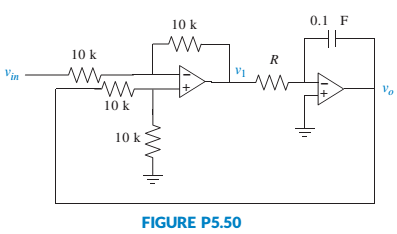
Assume ideal operational amplifiers in the circuit of Figure P5.50.
a. Show that the leftmost operational amplifier works as a subtracting amplifier. Namely,
b. Draw a block diagram of the system, with the subtracting amplifier represented with a summing junction, and the circuit of the rightmost operational amplifier with a transfer function in the forward path. Keep R as a variable.
c. Obtain the system’s closed-loop transfer function.
d. For a unit step input, obtain the value of R that will result in a settling time Ts= 1 msec.
e. Using the value of R calculated in Part d, make a sketch of the resulting unit step response.
Want to see the full answer?
Check out a sample textbook solution
Chapter 5 Solutions
Control Systems Engineering


- Problem 1: Write the transfer function of the systems. Problem 2: Write the differential equation and state space equation describing the following system. Please answer both the problems.arrow_forwardThe transfer function of a system is the ratio between _________________ and ____________ in Laplace transform. a. Output and Input b. Input and Output c. Input and Feedback d. Output and Feedbackarrow_forwardThe ratio of output to input of a system in Laplace domain is known as Transfer function . Select one: True Falsearrow_forward
- Find the time response of the one-step function of a system that has a transfer function in the forwardarrow_forwardGiven the system equipped with unitary feedback, whose direct branch transfer function is: Design a PID controller with one of the Ziegler-Nichols methods.arrow_forwardFind the transfer function C(s)/R(s) by block-reduction technique.arrow_forward
- A vibrating spring-mass system has the feedback control system shown in Fig Q3 below. (figure attached as image ACT)If K = 12.25 determine:6.1 the transfer function ; (3)6.2 the characteristic equation with a impulse input; (1)6.3 the un-damped natural frequency of the system; (2)6.4 the damping ratio; (2)6.5 the damped natural frequency; (2)6.6 the maximum percentage overshoot; (2)6.7 the peak time; (1)6.8 the settling time for the response within 2%. (2)arrow_forwardFind the transfer function,G(s)=Z1(s)/H(s) Find the state space model.arrow_forwardThis question asks for matrix form and NOT state space, but I don't understand what the difference between the two are.arrow_forward
- The magnitude of the steady-state response of an under damper and unforced spring-mass isarrow_forward1) Obtain a state space model of the system. 2) Given m =1 kg, k = 1 N/m and b = 1 N.s/m is the system Controllable? 3) For what values of k,m,b the system is stable? Explain your answer?arrow_forwardReduce the block diagram shown in Figure below to a single transfer function, T(s) = C(s)/R(s) Use the block diagram reduction method.arrow_forward
 Elements Of ElectromagneticsMechanical EngineeringISBN:9780190698614Author:Sadiku, Matthew N. O.Publisher:Oxford University Press
 Mechanics of Materials (10th Edition)Mechanical EngineeringISBN:9780134319650Author:Russell C. HibbelerPublisher:PEARSON
 Thermodynamics: An Engineering ApproachMechanical EngineeringISBN:9781259822674Author:Yunus A. Cengel Dr., Michael A. BolesPublisher:McGraw-Hill Education
 Control Systems EngineeringMechanical EngineeringISBN:9781118170519Author:Norman S. NisePublisher:WILEY
 Mechanics of Materials (MindTap Course List)Mechanical EngineeringISBN:9781337093347Author:Barry J. Goodno, James M. GerePublisher:Cengage Learning
 Engineering Mechanics: StaticsMechanical EngineeringISBN:9781118807330Author:James L. Meriam, L. G. Kraige, J. N. BoltonPublisher:WILEY