
Concept explainers
Videos
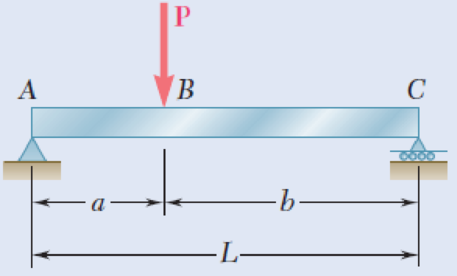
5.1 through 5.6 For the beam and loading shown, (a) draw the shear and bending-moment diagrams, (b) determine the equations of the shear and bending-moment curves.
Fig. P5.2
(a)
To draw: The shear and bending-moment diagrams.
Explanation of Solution
Determine the reactions of the beam.
Show the free-body diagram of the entire beam as in Figure 1.
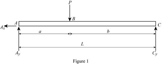
Determine the vertical reaction at point C by taking moment about point A.
Determine the vertical reaction at point A by resolving the vertical component of forces.
Substitute
Determine the horizontal direction at point A by resolving the horizontal component of forces.
Show the free-body diagram of the section 1-1 and 2-2 as in Figure 2.

Section 1-1:
Determine the shear force at the section by resolving the vertical component of forces.
Determine the moment at the section by taking moment about the section.
Section 2-2:
Determine the shear force at the section by resolving the vertical component of forces.
Determine the moment at the section by taking moment about the section.
Show the free-body diagram of the section 3-3 and 4-4 as in Figure 3.
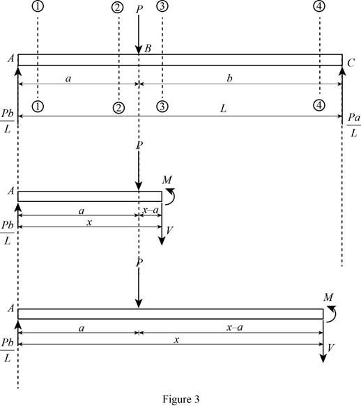
Section 3-3:
Determine the shear force at the section by resolving the vertical component of forces.
Determine the moment at the section by taking moment about the section.
When the section 3-3 is at point B,
Section 4-4:
Determine the shear force at the section by resolving the vertical component of forces.
Determine the moment at the section by taking moment about the section.
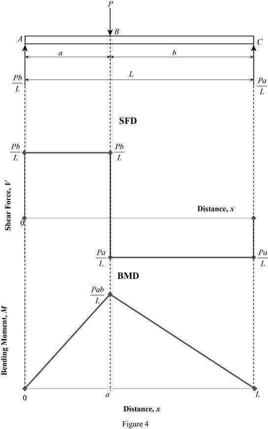
Shear force and bending moment values:
Show the calculated shear force and bending moment values as in Table 1.
| Location (x) | Shear force (V) | Bending Moment (M) |
| 1-1 | 0 | |
| 2-2 | ||
| 3-3 | ||
| 4-4 | 0 |
Plot the shear force and bending moment diagrams as in Figure 4.
(b)
The equations of the shear and bending-moment curves.
Answer to Problem 2P
The equation of shear force and bending-moment curves is:
For section AB;
For section BC;
Explanation of Solution
Determine the reactions of the beam.
Show the free-body diagram of the entire beam as in Figure 5.

Determine the vertical reaction at point C by taking moment about point A.
Determine the vertical reaction at point A by resolving the vertical component of forces.
Substitute
Determine the horizontal direction at point A by resolving the horizontal component of forces.
Show the free-body diagram of the section 1-1 and 2-2 as in Figure 6.
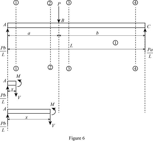
Section 1-1:
Determine the shear force at the section by resolving the vertical component of forces.
Determine the moment at the section by taking moment about the section.
Section 2-2:
Determine the shear force at the section by resolving the vertical component of forces.
Determine the moment at the section by taking moment about the section.
Show the free-body diagram of the section 3-3 and 4-4 as in Figure 7.

Section 3-3:
Determine the shear force at the section by resolving the vertical component of forces.
Determine the moment at the section by taking moment about the section.
When the section 3-3 is at point B,
Section 4-4:
Determine the shear force at the section by resolving the vertical component of forces.
Determine the moment at the section by taking moment about the section.
Therefore, the equation of shear force and bending-moment curves is:
For section AB;
For section BC;
Want to see more full solutions like this?
Chapter 5 Solutions
MECHANICS OF MATERIALSW/CONNECT>(LL)<>


- Two small channel sections DF and EH have been welded to the uniform beam AB of weight W = 3 kN to form the rigid structural member shown. This member is being lifted by two cables attached at D and E . Knowing that 0= 30° and neglecting the weight of the channel sections, (a) draw the shear and bending-moment diagrams for beam AB, (b) determine the maximum absolute values of the shear and bending moment in the beam.arrow_forwardDraw the shear and bending-moment diagrams for the beam and loading shown, and determine the maximum absolute value (a) of the shear, (b) of the bendingarrow_forwardDraw the shear and bending-moment diagrams for the beam and loading shown, and determine the maximum absolute value (a) of the shear, (b) of the bending momentarrow_forward
- Determine (a) the distance a for which the maximum absolute value of the bending moment in the beam is as small as possible, (b) the corresponding maximum normal stress due to bending.arrow_forwardKnowing that P= 480 N,Q=320N determine (a) the distance a for which the absolute value of the bending moment in the beam is as small as possible, (b) the corresponding maximum normal stress due to bending.arrow_forwardSolve Prob. 7.89 assuming that the bending moment was found to be +650 N.m at D and +1450 N.m at E.(Reference to Problem 7.89):The beam AB is subjected to the uniformly distributed load shown and to two unknown forces P and Q . Knowing that it has been experimentally determined that the bending moment is +800 N.m at D and +1300 at E, (a) determine P and Q,(b) draw the shear and bending-moment diagrams for the beam.arrow_forward
- Problem 03: Draw the shear and bending-moment diagrams for the beam and loading shown, and determine the maximum absolute value (a) of the shear, (b) of the bending moment.arrow_forwardThree boards, each of 1.5 x3.5-in. rectangular cross section, are nailed together to form a beam that is subjected to a vertical shear of 250 lb. Knowing that the spacing between each pair of nails is 2.5 in., determine the shearing force in each nail.arrow_forwardA weightlifting bar is loaded symmetrically in A and D (P = 1500N of each side). The weightlifter's hands are located at B and C, 0.45 m from A and D. Determine the maximum bending moment in the bar ABCD and the minimum diameter d of the bar knowing that the constraint admissible for the material of the bar is 200MPa.arrow_forward
- Knowing that P=Q= 480 N, determine (a) the distance a for which the absolute value of the bending moment in the beam is as small as possible, (b) the corresponding maximum normal stress due to bending.arrow_forwardA 12-m simply supported overhang beam is supported at x = 0 and x = 10m. The overhanging portion is from x = 10m to x = 12m (the overhang portion is 2m). Two equal wheel loads of 20kN each, separated by 2m roll as a unit across the 12-m span. Determine the maximum shear developed in the span.arrow_forwardFor the beam and loading shown, determine the maximum absolute values of the shear and bending momentarrow_forward
 Elements Of ElectromagneticsMechanical EngineeringISBN:9780190698614Author:Sadiku, Matthew N. O.Publisher:Oxford University Press
 Mechanics of Materials (10th Edition)Mechanical EngineeringISBN:9780134319650Author:Russell C. HibbelerPublisher:PEARSON
 Thermodynamics: An Engineering ApproachMechanical EngineeringISBN:9781259822674Author:Yunus A. Cengel Dr., Michael A. BolesPublisher:McGraw-Hill Education
 Control Systems EngineeringMechanical EngineeringISBN:9781118170519Author:Norman S. NisePublisher:WILEY
 Mechanics of Materials (MindTap Course List)Mechanical EngineeringISBN:9781337093347Author:Barry J. Goodno, James M. GerePublisher:Cengage Learning
 Engineering Mechanics: StaticsMechanical EngineeringISBN:9781118807330Author:James L. Meriam, L. G. Kraige, J. N. BoltonPublisher:WILEY