
Concept explainers
Videos
(a)
Write the equations for shear force and bending moments based on singularity function.
(a)
Answer to Problem 109P
The equation of shear force as a singularity function is;
The equation of bending moment as a singularity function is;
Explanation of Solution
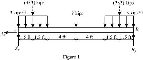
Show the free-body diagram of the beam as in Figure 1.
Determine the vertical reaction at point B by taking moment about point A.
Determine the vertical reaction at point A by resolving the vertical component of forces.
Write the equation of the load function as follows;
The equation for shear force as a function of load is,
Integrate the equation (1) to find V;
The equation for bending moment as a function of shear force is,
Integrate the equation (1) to find M;
Therefore,
The equation of shear force as a singularity function is,
The equation of bending moment as a singularity function is,
(b)
The maximum bending moment using the singularity function.
(b)
Answer to Problem 109P
The maximum bending moment in the beam is
Explanation of Solution
Refer to Equation (2), find the location of maximum bending moment where the shear force changes sign. i.e.,
Point A
Substitute 0 ft for x in Equation (2).
Point C
Substitute 3 ft for x in Equation (2).
Point D
Substitute 7 ft for x in Equation (2).
Point E
Substitute 11 ft for x in Equation (2).
Point B
Substitute 14 ft for x in Equation (2).
Refer to the calculated shear force values, the shear force changes at point D.
Refer to Equation (3).
Substitute 7 ft for x in Equation (3).
Therefore, the maximum bending moment in the beam is
Want to see more full solutions like this?
Chapter 5 Solutions
MECHANICS OF MATERIALSW/CONNECT>(LL)<>


- Two small channel sections DF and EH have been welded to the uniform beam AB of weight W = 3 kN to form the rigid structural member shown. This member is being lifted by two cables attached at D and E . Knowing that 0= 30° and neglecting the weight of the channel sections, (a) draw the shear and bending-moment diagrams for beam AB, (b) determine the maximum absolute values of the shear and bending moment in the beam.arrow_forwardFor the beam and loading shown, determine the maximum absolute values of the shear and bending momentarrow_forwardDraw the shear and bending-moment diagrams for the beam and loading shown, and determine the maximum absolute value (a) of the shear, (b) of the bending momentarrow_forward
- Determine (a) the distance a for which the maximum absolute value of the bending moment in the beam is as small as possible, (b) the corresponding maximum normal stress due to bending.arrow_forwardDraw the shearing-force and bending-moment diagrams for the following beams: A cantilever of length 20 m carrying a load of 10 kN at a distance of 15 m from the supported end. A cantilever of length 20 m carrying a load of 10 kN uniformly distributed over the inner 15 m of its length. A cantilever of length 12 m carrying a load of 8 kN, applied 5 m from the supported end, and a load of 2kN/m over its whole length.arrow_forwardDraw the shear and bending-moment diagrams for the beam and loading shown, and determine the maximum absolute value (a) of the shear, (b) of the bendingarrow_forward
- A 12-m simply supported overhang beam is supported at x = 0 and x = 10m. The overhanging portion is from x = 10m to x = 12m (the overhang portion is 2m). Two equal wheel loads of 20kN each, separated by 2m roll as a unit across the 12-m span. Determine the maximum shear developed in the span.arrow_forwardA weightlifting bar is loaded symmetrically in A and D (P = 1500N of each side). The weightlifter's hands are located at B and C, 0.45 m from A and D. Determine the maximum bending moment in the bar ABCD and the minimum diameter d of the bar knowing that the constraint admissible for the material of the bar is 200MPa.arrow_forwardFor the beam and loading shown, determine the absolute values of the shear and bending moment at 2.5 m to the left of point B.arrow_forward
- A beam is carrying a moment M as indicated. The cross section of the beam is symmetric about the z axis. The dimensions of the cross section and the location of the centroid (point C) are shown. Knowing that Iy = 280,000 mm4, Iz = 150,000 mm4, and M = 400,000 + UV in N.mm, where UV is 21(a) Calculate the components of the bending moment on the y and z axes, Myand Mz.(b) Identify which point at the cross section has the largest tensile stress, and which point at the cross section has the largest compressive stress.(c) Calculate the maximum tensile stress and the maximum compressive stress in the cross sectionarrow_forwardFor the beam and loading shown, determine the maximum absolute value of bending moment and sheararrow_forwardKnowing the vertical reaction at the roller support at C of the beam shown is 12.5 kN upward, determine the requested algebraic expressions for shear and moment (in terms of the variable x), using the proper sign conventions established for drawing the shear and bending moment diagrams. (a) The shear and moment equations (in terms of the variable x) for the left region of the beam between points A and B, using the F.B.D. of the left-side of your considered cut section (b) The shear and moment equations (in terms of the variable x) for the right region of the beam between points B and C using the F.B.D. of the right-side of your considered cut section.please show all steps and FBD.arrow_forward
 Elements Of ElectromagneticsMechanical EngineeringISBN:9780190698614Author:Sadiku, Matthew N. O.Publisher:Oxford University Press
 Mechanics of Materials (10th Edition)Mechanical EngineeringISBN:9780134319650Author:Russell C. HibbelerPublisher:PEARSON
 Thermodynamics: An Engineering ApproachMechanical EngineeringISBN:9781259822674Author:Yunus A. Cengel Dr., Michael A. BolesPublisher:McGraw-Hill Education
 Control Systems EngineeringMechanical EngineeringISBN:9781118170519Author:Norman S. NisePublisher:WILEY
 Mechanics of Materials (MindTap Course List)Mechanical EngineeringISBN:9781337093347Author:Barry J. Goodno, James M. GerePublisher:Cengage Learning
 Engineering Mechanics: StaticsMechanical EngineeringISBN:9781118807330Author:James L. Meriam, L. G. Kraige, J. N. BoltonPublisher:WILEY