Concept explainers
Videos
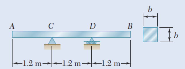
A solid steel bar has a square cross section of side b and is supported as shown. Knowing that for steel ρ = 7860 kg/m3, determine the dimension b for which the maximum normal stress due to bending is (a) 10 MPa, (b) 50 MPa.
Fig. P5.33
(a)
the dimension b.
Answer to Problem 33P
The dimension b of the square cross section is
Explanation of Solution
Given information:
The maximum normal stress due to bending is 10 MPa.
Determine the weight density
Here, the mass density of the bar is
Consider the acceleration due to gravity as
Substitute
Determine the dead load (W) of the solid steel bar using the relation.
Here, the cross sectional area of the steel bar is A, the length of the beam is L, and the dimension of the bar is d.
Convert the mass density into weight density as follows;
Substitute
Determine the reactions of the beam.
Show the free-body diagram of the beam as in Figure 1.
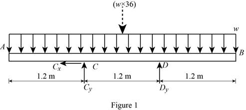
Determine the vertical reaction at point C by taking moment at point D.
Show the free-body diagram of the sections as in Figure 2.

Region AC (Section 1-1):
Determine the bending moment at the section by taking moment about the section.
Region CD (Section 2-2):
Determine the bending moment at the section by taking moment about the section.
Region DB (Section 3-3):
Determine the bending moment at the section by taking moment about the section.
Bending moment values:
Show the calculated bending moment values as in Table 1.
| Location (x) m | Bending moment (M) N-m |
| A (0 m) | 0 |
| C (1-1) (1.2 m) | –0.72w |
| C (2-2) (1.2 m) | –0.72w |
| Mid-point (1.8 m) | –0.54w |
| D (2-2) (2.4 m) | –0.72w |
| D (3-3) (2.4 m) | –0.72w |
| B (3.6 m) | 0 |
Plot the bending moment diagram as in Figure 3.

Refer to Figure 3;
The maximum bending moment is
Determine the section modulus (S) of the square section using the equation.
Determine the maximum normal stress
Substitute
Substitute 10 MPa for
Therefore, the dimension b of the square cross section is
(b)
the dimension b.
Answer to Problem 33P
The dimension b of the square cross section is
Explanation of Solution
Given information:
The maximum normal stress due to bending is 50 MPa.
Determine the weight density
Here, the mass density of the bar is
Consider the acceleration due to gravity as
Substitute
Determine the dead load (W) of the solid steel bar using the relation.
Here, the cross sectional area of the steel bar is A, the length of the beam is L, and the dimension of the bar is d.
Convert the mass density into weight density as follows;
Substitute
Determine the reactions of the beam.
Show the free-body diagram of the beam as in Figure 4.

Determine the vertical reaction at point C by taking moment at point D.
Show the free-body diagram of the sections as in Figure 5.
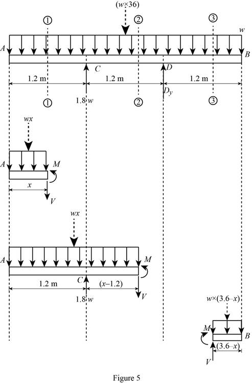
Region AC (Section 1-1):
Determine the bending moment at the section by taking moment about the section.
Region CD (Section 2-2):
Determine the bending moment at the section by taking moment about the section.
Region DB (Section 3-3):
Determine the bending moment at the section by taking moment about the section.
Bending moment values:
Show the calculated bending moment values as in Table 2.
| Location (x) m | Bending moment (M) N-m |
| A (0 m) | 0 |
| C (1-1) (1.2 m) | –0.72w |
| C (2-2) (1.2 m) | –0.72w |
| Mid-point (1.8 m) | –0.54w |
| D (2-2) (2.4 m) | –0.72w |
| D (3-3) (2.4 m) | –0.72w |
| B (3.6 m) | 0 |
Plot the bending moment diagram as in Figure 6.
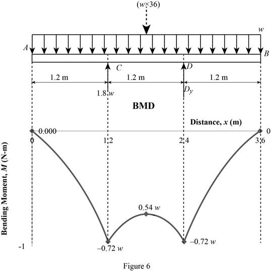
Refer to the Figure 6;
The maximum bending moment is
Determine the section modulus (S) of the square section using the equation.
Determine the maximum normal stress
Substitute
Substitute 50 MPa for
Therefore, the dimension b of the square cross section is
Want to see more full solutions like this?
Chapter 5 Solutions
Mechanics of Materials - With Access


- Knowing that P=Q= 480 N, determine (a) the distance a for which the absolute value of the bending moment in the beam is as small as possible, (b) the corresponding maximum normal stress due to bending.arrow_forwardA solid steel rod of diameter d is supported as shown. Knowing that for steel γ= 490 lb/ft3, determine the smallest diameter d that can be used if the normal stress due to bending is not to exceed 4 ksiarrow_forwardDetermine (a) the distance a for which the absolute value of the bending moment in the beam is as small as possible, (b) the corresponding moximum normal stress due to bending.arrow_forward
- A) The four cross sections shown have different characteristics when subjected to a vertical shear force. Which of the four geometries shown has the largest value for the moment of the area, Q, about the neutral axis? B) Which of the four geometries shown has the smallest value for its moment of inertia about the x axis? C) Given that all four geometries are subjected to the same vertical shear force V, which of the four has the smallest value for the maximum shear stress?arrow_forwardA fabric used in air-inflated structures is subjected to a biaxial loading that results in normal stresses ox = 18 ksi and oz = 24 ksi.Knowing that the properties of the fabric can be approximated as E = 12.6 x 10 psi and v = 0.34, determine the change in length of (a) side AB, (b) side BC, (c) diagonal AC.arrow_forwardThe rectangular tube shown is extruded from an aluminum alloy for which σY= 40 ksi, σU= 60 ksi, and E= 10.6 * 106 psi. Neglecting the effect of fillets, determine (a) the bending moment M for which the factor of safety will be 3.00 and (b) the corresponding radius of curvature of the tubearrow_forward
- Link AB, of width b = 50 mm and thickness t = 6 mm, is used to support the end of a horizontal beam. Knowing that the average normal stress in the link is –140 MPa, and that the average shearing stress in each of the two pins is 80 MPa, determine (a) the diameter d of the pins, (b) the average bearing stress in the link.arrow_forwardFor the beam with the cross-section shown, given that: V= 100 N b= 20 cm h=20 cm The max shear stress equals:arrow_forwardEach of the three aluminum bars shown is to be twisted through an angle of 2.1°. Knowing that b = 30 mm, τall = 50 MPa, and G = 27 GPa, determine the shortest allowable length of each bar. Refer to Table 3.1. The shortest allowable length of bar (a) is mm. The shortest allowable length of bar (b) is mm. The shortest allowable length of bar (c) is mm.arrow_forward
- Draw the shearing-force and bending-moment diagrams for the following beams: A cantilever of length 20 m carrying a load of 10 kN at a distance of 15 m from the supported end. A cantilever of length 20 m carrying a load of 10 kN uniformly distributed over the inner 15 m of its length. A cantilever of length 12 m carrying a load of 8 kN, applied 5 m from the supported end, and a load of 2kN/m over its whole length.arrow_forwardFive metal strips, each of 0.5 * 1.5-in. cross section, are bonded together to form the composite beam shown. The modulus of elasticity is 30* 106 psi for the steel, 15 *106 psi for the brass, 10 *106 psi for the aluminum. Knowing that the beam is bent about a horizontal axis by a couple of moment 12 kip·in., determine (a) the maximum stress in each of the three metals, (b) the radius of curvature of the composite beam.arrow_forwardThree 1 x 18-in. steel plates are bolted to four L6 x 6 x 1 angles to form a beam with the cross section shown. The bolts have a 78-in. diameter and are spaced longitudinally every 5 in. Knowing that the allowable average shearing stress in the bolts is 12 ksi, determine the largest permissible vertical shear in the beam. (Given: Ix= 6123 in4.)arrow_forward
 Elements Of ElectromagneticsMechanical EngineeringISBN:9780190698614Author:Sadiku, Matthew N. O.Publisher:Oxford University Press
 Mechanics of Materials (10th Edition)Mechanical EngineeringISBN:9780134319650Author:Russell C. HibbelerPublisher:PEARSON
 Thermodynamics: An Engineering ApproachMechanical EngineeringISBN:9781259822674Author:Yunus A. Cengel Dr., Michael A. BolesPublisher:McGraw-Hill Education
 Control Systems EngineeringMechanical EngineeringISBN:9781118170519Author:Norman S. NisePublisher:WILEY
 Mechanics of Materials (MindTap Course List)Mechanical EngineeringISBN:9781337093347Author:Barry J. Goodno, James M. GerePublisher:Cengage Learning
 Engineering Mechanics: StaticsMechanical EngineeringISBN:9781118807330Author:James L. Meriam, L. G. Kraige, J. N. BoltonPublisher:WILEY