
STANDALONE CODE MECHANICS OF MATERIALS-M
11th Edition
ISBN: 9780137605200
Author: HIBBELER
Publisher: PEARSON
expand_more
expand_more
format_list_bulleted
Concept explainers
Videos
Textbook Question
Chapter 5.10, Problem 133P
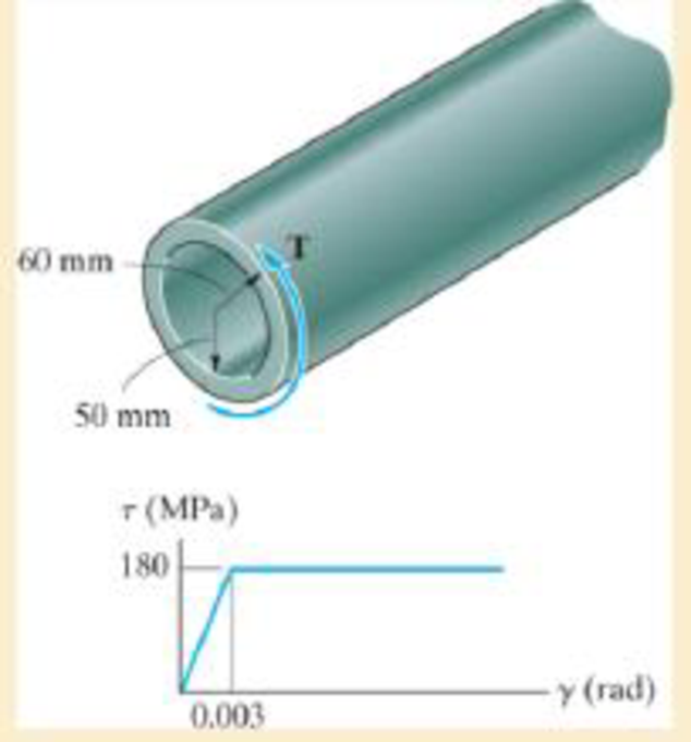
Determine the applied torque T, which subjects the material at the tube's outer edge to a shear strain of γmax = 0.006 rad. What would be the permanent angle of twist of the tube when this torque is removed? Sketch the residual stress distribution in the tube.
Expert Solution & Answer
Want to see the full answer?
Check out a sample textbook solution
Students have asked these similar questions
The 2-m-long tube is made of an elastic perfectly plastic material as shown. Determine the applied torque T, which subjects the material at the tube’s outer edge to a shear strain of gmax = 0.006 rad. What would be the permanent angle of twist of the tube when this torque is removed? Sketch the residual stress distribution in the tube
The solid-circular member AC, having a diameter D and a shear modulus of 69 GPa, is subjected to the torques 2T and 3T at points A and B, respectively. If tallow = 35 MPa and (fA/C)allow =2o, determine the maximum permissible value of the torque T.
Use the table given below and your student ID to find the values of L1, L2, and D.
Student ID
L1 (m)
L2 (m)
D (mm)
1131731
1
0.6
78
The shaft is made from a solid steel section AB and a tubular
portion made of steel and having a brass core. If it is fixed to a
rigid support at A, and a torque of T = 50 lb.ft is applied to it at
C, determine the rotation angle that occurs at C relative to A and
compute the maximum shear stress and maximum shear strain in
the brass and steel. Take Gst = 11500 ksi, Gbr = 5600 Ksi.
3 ft
0.5 in.
B
1 in.
T = 50 lb•ft
Chapter 5 Solutions
STANDALONE CODE MECHANICS OF MATERIALS-M
Ch. 5.3 - The solid circular shaft is subjected to an...Ch. 5.3 - The hollow circular shaft is subjected to an...Ch. 5.3 - The shaft is hollow from A to B and solid from B...Ch. 5.3 - Determine the maximum shear stress in the...Ch. 5.3 - Determine the maximum shear stress in the shaft at...Ch. 5.3 - Determine the shear stress a: point A on the...Ch. 5.3 - The solid 50-mm-diameter shaft is subjected to the...Ch. 5.3 - The gear motor can develop 3 hp when it turns at...Ch. 5.3 - The solid shaft of radius r is subjected to a...Ch. 5.3 - The solid shaft of radius r is subjected to a...
Ch. 5.3 - Prob. 3PCh. 5.3 - The copper pipe has an outer diameter of 40 mm and...Ch. 5.3 - The copper pipe has an outer diameter of 2.50 in....Ch. 5.3 - The link acts as part of the elevator control for...Ch. 5.3 - The assembly consists of two sections of...Ch. 5.3 - A steel tube having an outer diameter of 2.5 in....Ch. 5.3 - The rod has a diameter of 1 in. and a weight of 10...Ch. 5.3 - The rod has a diameter of 1 in. and a weight of 15...Ch. 5.3 - Prob. 20PCh. 5.3 - The 60-mm-diameter solid shaft is subjected to the...Ch. 5.3 - The 60-mm-diameter solid shaft is subjected to the...Ch. 5.3 - The solid shaft is subjected to the distributed...Ch. 5.3 - If the tube is made from a material having an...Ch. 5.3 - Prob. 29PCh. 5.3 - The motor delivers 50 hp while turning at a...Ch. 5.3 - The solid steel shaft AC has a diameter of 25 mm...Ch. 5.3 - Prob. 35PCh. 5.4 - The 60 mm-diameter steel shaft is subjected to the...Ch. 5.4 - Prob. 10FPCh. 5.4 - The hollow 6061-T6 aluminum shaft has an outer and...Ch. 5.4 - A series of gears are mounted on the...Ch. 5.4 - The 80-mm-diameter shaft is made of steel. If it...Ch. 5.4 - The 80-mm-diameter shaft is made of steel. If it...Ch. 5.4 - The propellers of a ship are connected to an A-36...Ch. 5.4 - Show that the maximum shear strain in the shaft is...Ch. 5.4 - Determine the angle of twist of end B with respect...Ch. 5.4 - Determine the maximum allowable torque T. Also,...Ch. 5.4 - If the allowable shear stress is allow = 80 MPa,...Ch. 5.4 - Determine the angle of twist of the end A.Ch. 5.4 - The hydrofoil boat has an A992 steel propeller...Ch. 5.4 - Also, calculate the absolute maximum shear stress...Ch. 5.4 - If a torque of T = 50 N m is applied to the bolt...Ch. 5.4 - If a torque of T= 50N m is applied to the bolt...Ch. 5.4 - If the motor delivers 4 MW of power to the shaft...Ch. 5.4 - Determine the angle of twist at the free end A of...Ch. 5.5 - Gst = 75 GPa.Ch. 5.5 - The shaft is made of L2 tool steel, has a diameter...Ch. 5.5 - Each has a diameter of 25 mm and they are...Ch. 5.5 - Each has a diameter of 25 mm and they are...Ch. 5.5 - It is fixed at its ends and subjected to a torque...Ch. 5.5 - 5–89. Determine the absolute maximum shear stress...Ch. 5.7 - If the yield stress for brass is Y = 205 MPa,...Ch. 5.7 - By what percentage is the shaft of circular cross...Ch. 5.7 - Prob. 97PCh. 5.7 - Also, find the angle of twist of end B. The shaft...Ch. 5.7 - Also, find the corresponding angle of twist at end...Ch. 5.7 - Prob. 110PCh. 5.7 - Determine the average shear stress in the tube if...Ch. 5.7 - By what percentage is the torsional strength...Ch. 5.7 - Prob. 114PCh. 5.7 - Prob. 115PCh. 5.7 - Prob. 119PCh. 5.10 - Prob. 121PCh. 5.10 - If the radius of the fillet weld connecting the...Ch. 5.10 - Prob. 125PCh. 5.10 - Determine the radius of the elastic core produced...Ch. 5.10 - Prob. 128PCh. 5.10 - Determine the torque T needed to form an elastic...Ch. 5.10 - Determine the torque applied to the shaft.Ch. 5.10 - Prob. 131PCh. 5.10 - Determine the ratio of the plastic torque Tp to...Ch. 5.10 - Determine the applied torque T, which subjects the...Ch. 5.10 - Determine the radius of its elastic core if it is...Ch. 5.10 - Plot the shear-stress distribution acting along a...Ch. 5.10 - If the material obeys a shear stress-strain...Ch. 5.10 - It is made of an elastic perfectly plastic...Ch. 5.10 - Prob. 139PCh. 5.10 - Prob. 140PCh. 5.10 - Prob. 142PCh. 5.10 - Prob. 143PCh. 5 - The shaft is made of A992 steel and has an...Ch. 5 - The shaft is made of A992 steel and has an...Ch. 5 - Determine the shear stress at the mean radius p =...Ch. 5 - If the thickness of its 2014-T6-aluminum skin is...Ch. 5 - Determine which shaft geometry will resist the...Ch. 5 - If couple forces P = 3 kip are applied to the...Ch. 5 - If the allowable shear stress for the aluminum is...Ch. 5 - Determine the angle of twist of its end A if it is...Ch. 5 - This motion is caused by the unequal belt tensions...
Knowledge Booster


Learn more about
Need a deep-dive on the concept behind this application? Look no further. Learn more about this topic, mechanical-engineering and related others by exploring similar questions and additional content below.Similar questions
- A torque of 2 kip # in. is applied to the tube. If the wall thickness is 0.1 in., determine the average shear stress in the tube.arrow_forwardTwo forces, each of magnitude P, are applied to the wrench. The diameter of the steel shaft AB is 30mm. Determine the largest allowable value of P if the shear stress in the shaft is not to exceed 120MPa and it's angle of twist is limited to 7deg. Use G=83GPa for steel. -Draw and label the diagram correctly, No diagram in the solution will be marked wrong. -Shortcut solution will be marked wrong.arrow_forwardThe copper pipe has an outer diameter of 40 mm and an inner diameter of 37 mm. If it is tightly secured to the wall at A and 3 torques are applied to it as shown, determine the absolute maximum shear stress developed in the pipe. Given the shear modulus G = 37 GPa for copper and the segmental lengths of the pipe, calculate the angle of twist of point D with respect to point A| B Length: AB = 0.6 m ´ 30 N-m 20 N-m BC = 0.6 m CD = 1.2 m 80 N-marrow_forward
- The halves of the coupling are held together by four 5/8-in.-diameter bolts. The working stresses are 12 ksi for shear in the bolts and 15 ksi for bearing in the coupling. Find the largest torque T that can be safely transmitted by the coupling. Assume that the forces in the bolts have equal magnitudes. 0.5 in. 3.5 in.arrow_forwardThe copper pipe has an outer diameter of 40 mm and an inner diameter of 34 mm. It is tightly secured to the wall at A and three torques are applied to it as shown in the figure below. (Figure 1) Figure 80 N.m A 20 N-m 30 N-m < 1 of 1 ▼ Part A Determine the absolute maximum shear stress developed in the pipe. Express your answer to three significant figures and include the appropriate units. Tmax= Value Submit μÀ Provide Feedback Request Answer DW Unitsarrow_forwardThe stepped steel shaft carries the torque T. Determine the allowable magnitude of T if the working shear stress is 22 MPa and the and the rotation of the free end is limited to 5.2°. Use G = 83 GPA. Show the free body diagram.arrow_forward
- The tube is made of C86100 bronze and has a rectangular cross section asshown in Figure. If it is subjected to the two torques, determine the average shear stress in the tube at points A and B. Also, what is the angle of twist of end C? The tube is fixed at E.arrow_forwardThe cylinder of a hydraulic ram supported at the open end is 200 mm internal diameter and is required to sustain an internal pressure of 25 MN/m2.Calculate the necessary thickness of the wall if the maximum shearing stress is limited to 55 MN/m2.Allowing for the effect of the longitudinal stress caused by the pressure on the end of the cylinder, calculate the increase in diameter due to the application of the 25 MN/m2 pressure. Take E= 214 GN/m2 and υ = 0. 28arrow_forwardThe steel step shaft has an allowable shear stress of Fallow 9 MPa. If the transition between the cross-sections has a radius r-4 mm, determine the maximum torque T that can be applied. Take K-1.25. 20 mm 72 N.m T 50 mm 20 mm 7/2 The maximum torque T that can be applied is. Note: Please enter your answer with three significant digits after the decimal point. Take the torque as positive since the problem does not have multiple sections before the step.arrow_forward
- The stepped steel shaft carries the torque T. Determine the maximum allowable magnitude of T if the working shear stress is 14 MPa and the rotation of the free end is limited to 3.50 . Use G = 83 GPa for steelarrow_forwardTwo forces, each of magnitude P, are applied to the wrench. The diameter of the steel shaft AB is 15 mm. Determine the largest allowable value of P if the shear stress in the shaft is not to exceed 120 MPa and its angle of twist is limited to 5°. Use G = 80 GPa for steel. 300 mm P B 500 mm Aarrow_forwardQ4 An aluminium tube, 1.2 m long, has the semi-circular crossection shown in the fig. If the stress concentrations are neglected at the corners, determine (a) the torque that causes a maximum shear stress of 35MPa and (b) the corresponding angle of twist of the tube. Use G=26GPA for aluminium. 2 mm 25 mm 3 mm Fig 4: Aluminium Tubearrow_forward
arrow_back_ios
SEE MORE QUESTIONS
arrow_forward_ios
Recommended textbooks for you
 Elements Of ElectromagneticsMechanical EngineeringISBN:9780190698614Author:Sadiku, Matthew N. O.Publisher:Oxford University Press
 Mechanics of Materials (10th Edition)Mechanical EngineeringISBN:9780134319650Author:Russell C. HibbelerPublisher:PEARSON
 Thermodynamics: An Engineering ApproachMechanical EngineeringISBN:9781259822674Author:Yunus A. Cengel Dr., Michael A. BolesPublisher:McGraw-Hill Education
 Control Systems EngineeringMechanical EngineeringISBN:9781118170519Author:Norman S. NisePublisher:WILEY
 Mechanics of Materials (MindTap Course List)Mechanical EngineeringISBN:9781337093347Author:Barry J. Goodno, James M. GerePublisher:Cengage Learning
 Engineering Mechanics: StaticsMechanical EngineeringISBN:9781118807330Author:James L. Meriam, L. G. Kraige, J. N. BoltonPublisher:WILEY
Elements Of Electromagnetics
Mechanical Engineering
ISBN:9780190698614
Author:Sadiku, Matthew N. O.
Publisher:Oxford University Press
Mechanics of Materials (10th Edition)
Mechanical Engineering
ISBN:9780134319650
Author:Russell C. Hibbeler
Publisher:PEARSON
Thermodynamics: An Engineering Approach
Mechanical Engineering
ISBN:9781259822674
Author:Yunus A. Cengel Dr., Michael A. Boles
Publisher:McGraw-Hill Education
Control Systems Engineering
Mechanical Engineering
ISBN:9781118170519
Author:Norman S. Nise
Publisher:WILEY
Mechanics of Materials (MindTap Course List)
Mechanical Engineering
ISBN:9781337093347
Author:Barry J. Goodno, James M. Gere
Publisher:Cengage Learning
Engineering Mechanics: Statics
Mechanical Engineering
ISBN:9781118807330
Author:James L. Meriam, L. G. Kraige, J. N. Bolton
Publisher:WILEY
Pressure Vessels Introduction; Author: Engineering and Design Solutions;https://www.youtube.com/watch?v=Z1J97IpFc2k;License: Standard youtube license