
STANDALONE CODE MECHANICS OF MATERIALS-M
11th Edition
ISBN: 9780137605200
Author: HIBBELER
Publisher: PEARSON
expand_more
expand_more
format_list_bulleted
Concept explainers
Videos
Textbook Question
Chapter 5.3, Problem 1P
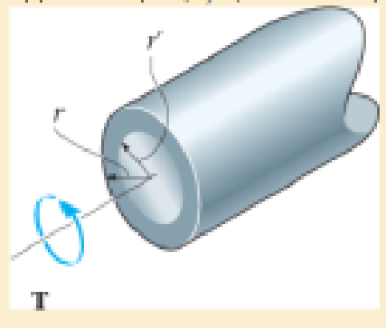
The solid shaft of radius r is subjected to a torque T. Determine the radius r' of the inner core of the shaft that resists one-half of the applied torque (T/2). Solve the problem two ways: (a) by using the torsion formula, (b) by finding the resultant of the shear-stress distribution.
Expert Solution & Answer
Want to see the full answer?
Check out a sample textbook solution
Students have asked these similar questions
The solid shaft of radius r is subjected to a torque T. Determine the radius r
of the inner core of the shaft that resists one-half of the applied torque (T>2). Solve the problem two ways: (a) by using the torsion formula, (b) by finding the resultant of the shear-stress distribution.
The axis ABCD receives a torque of 500Nm from the motor and transmits movement to other devices, by means of belts and pulleys connected at B and C. If it is known that the torques exerted on pulleys B and C are as shown In the figure, determine the minimum radius the shaft must have. You should consider that at point D of the motor there is a bearing that acts as a support for the shaft as at point A. The material of the shaft and its allowable shear stress are indicated in the drawing.Determine:to. Free-Body diagram.b. Shear force diagrams.c. Bending moment diagrams.d. Identification of the critical point of the axis.e. Calculation of the axis radius.
tperm=80MPa
A steel shaft of diameter 60 mm and length 3.5 m is fixed at its ends A and B. If two torques of the same direction are applied, a 500 Nm torque at C (Im from the left end) and a 200 Nm torque at D (1m from the right end), determine the maximum internal torque in the shaft.
Chapter 5 Solutions
STANDALONE CODE MECHANICS OF MATERIALS-M
Ch. 5.3 - The solid circular shaft is subjected to an...Ch. 5.3 - The hollow circular shaft is subjected to an...Ch. 5.3 - The shaft is hollow from A to B and solid from B...Ch. 5.3 - Determine the maximum shear stress in the...Ch. 5.3 - Determine the maximum shear stress in the shaft at...Ch. 5.3 - Determine the shear stress a: point A on the...Ch. 5.3 - The solid 50-mm-diameter shaft is subjected to the...Ch. 5.3 - The gear motor can develop 3 hp when it turns at...Ch. 5.3 - The solid shaft of radius r is subjected to a...Ch. 5.3 - The solid shaft of radius r is subjected to a...
Ch. 5.3 - Prob. 3PCh. 5.3 - The copper pipe has an outer diameter of 40 mm and...Ch. 5.3 - The copper pipe has an outer diameter of 2.50 in....Ch. 5.3 - The link acts as part of the elevator control for...Ch. 5.3 - The assembly consists of two sections of...Ch. 5.3 - A steel tube having an outer diameter of 2.5 in....Ch. 5.3 - The rod has a diameter of 1 in. and a weight of 10...Ch. 5.3 - The rod has a diameter of 1 in. and a weight of 15...Ch. 5.3 - Prob. 20PCh. 5.3 - The 60-mm-diameter solid shaft is subjected to the...Ch. 5.3 - The 60-mm-diameter solid shaft is subjected to the...Ch. 5.3 - The solid shaft is subjected to the distributed...Ch. 5.3 - If the tube is made from a material having an...Ch. 5.3 - Prob. 29PCh. 5.3 - The motor delivers 50 hp while turning at a...Ch. 5.3 - The solid steel shaft AC has a diameter of 25 mm...Ch. 5.3 - Prob. 35PCh. 5.4 - The 60 mm-diameter steel shaft is subjected to the...Ch. 5.4 - Prob. 10FPCh. 5.4 - The hollow 6061-T6 aluminum shaft has an outer and...Ch. 5.4 - A series of gears are mounted on the...Ch. 5.4 - The 80-mm-diameter shaft is made of steel. If it...Ch. 5.4 - The 80-mm-diameter shaft is made of steel. If it...Ch. 5.4 - The propellers of a ship are connected to an A-36...Ch. 5.4 - Show that the maximum shear strain in the shaft is...Ch. 5.4 - Determine the angle of twist of end B with respect...Ch. 5.4 - Determine the maximum allowable torque T. Also,...Ch. 5.4 - If the allowable shear stress is allow = 80 MPa,...Ch. 5.4 - Determine the angle of twist of the end A.Ch. 5.4 - The hydrofoil boat has an A992 steel propeller...Ch. 5.4 - Also, calculate the absolute maximum shear stress...Ch. 5.4 - If a torque of T = 50 N m is applied to the bolt...Ch. 5.4 - If a torque of T= 50N m is applied to the bolt...Ch. 5.4 - If the motor delivers 4 MW of power to the shaft...Ch. 5.4 - Determine the angle of twist at the free end A of...Ch. 5.5 - Gst = 75 GPa.Ch. 5.5 - The shaft is made of L2 tool steel, has a diameter...Ch. 5.5 - Each has a diameter of 25 mm and they are...Ch. 5.5 - Each has a diameter of 25 mm and they are...Ch. 5.5 - It is fixed at its ends and subjected to a torque...Ch. 5.5 - 5–89. Determine the absolute maximum shear stress...Ch. 5.7 - If the yield stress for brass is Y = 205 MPa,...Ch. 5.7 - By what percentage is the shaft of circular cross...Ch. 5.7 - Prob. 97PCh. 5.7 - Also, find the angle of twist of end B. The shaft...Ch. 5.7 - Also, find the corresponding angle of twist at end...Ch. 5.7 - Prob. 110PCh. 5.7 - Determine the average shear stress in the tube if...Ch. 5.7 - By what percentage is the torsional strength...Ch. 5.7 - Prob. 114PCh. 5.7 - Prob. 115PCh. 5.7 - Prob. 119PCh. 5.10 - Prob. 121PCh. 5.10 - If the radius of the fillet weld connecting the...Ch. 5.10 - Prob. 125PCh. 5.10 - Determine the radius of the elastic core produced...Ch. 5.10 - Prob. 128PCh. 5.10 - Determine the torque T needed to form an elastic...Ch. 5.10 - Determine the torque applied to the shaft.Ch. 5.10 - Prob. 131PCh. 5.10 - Determine the ratio of the plastic torque Tp to...Ch. 5.10 - Determine the applied torque T, which subjects the...Ch. 5.10 - Determine the radius of its elastic core if it is...Ch. 5.10 - Plot the shear-stress distribution acting along a...Ch. 5.10 - If the material obeys a shear stress-strain...Ch. 5.10 - It is made of an elastic perfectly plastic...Ch. 5.10 - Prob. 139PCh. 5.10 - Prob. 140PCh. 5.10 - Prob. 142PCh. 5.10 - Prob. 143PCh. 5 - The shaft is made of A992 steel and has an...Ch. 5 - The shaft is made of A992 steel and has an...Ch. 5 - Determine the shear stress at the mean radius p =...Ch. 5 - If the thickness of its 2014-T6-aluminum skin is...Ch. 5 - Determine which shaft geometry will resist the...Ch. 5 - If couple forces P = 3 kip are applied to the...Ch. 5 - If the allowable shear stress for the aluminum is...Ch. 5 - Determine the angle of twist of its end A if it is...Ch. 5 - This motion is caused by the unequal belt tensions...
Knowledge Booster


Learn more about
Need a deep-dive on the concept behind this application? Look no further. Learn more about this topic, mechanical-engineering and related others by exploring similar questions and additional content below.Similar questions
- The compound shaft carries the two torques shown. The shear moduli are 28 GPa for aluminum, 83 GPa for steel, and 35 Gpa for bronze. If T = 1168.7 Nm, U = 4515 Nm, x = 3.01 m, y = 2.36 m, z = 1.35 m, d = 90 mm, and e = 83 mm, find the angle of rotation of the free end of the shaft. Round off the final answer to two decimal places. U T Aluminum Steel Bronzearrow_forwardThe copper pipe has an outer diameter of 2.5 in. and an inner diameter of 2.25 in. It is tightly secured to the wall at C and a uniformly distributed torque is applied to it as shown.(Figure 1) Points A and B lie on the pipe's outer surface. Figure C B |--M 2 ft V 150 lb-ft/ft. TIM A 2 ft V -- < 1 of 1 Determine the shear stress at point A. Express your answer to three significant figures and include appropriate units. TA = ΤΑ Submit Part B O — μA 4 TB = Value Units Previous Answers Request Answer X Incorrect; Try Again; 4 attempts remaining μA P Determine the shear stress at point B. Express your answer to three significant figures and include appropriate units. Value Units ? www ? Submit Previous Answers Request Answerarrow_forwardThe aluminum shaft, composed of three segments is fastened to rigid supports as A and D. Calculate the maximum shear stress in each segment when the two torques are applied. A 400 N-m 850 N-m L=1.4 m 30 mm diameter B L=2.4 m 50 mm diameter L-1.9 m 30 mm diameterarrow_forward
- A compound shaft consists of two pipe segments. Segment (1) has an outside diameter of 212 mm and a wall thickness of 9 mm. Segment (2) has an outside diameter of 139 mm and a wall thickness of 11 mm. The shaft is subjected to torques TB = 47 kN-m and Tc = 24 kN-m, which act in the directions shown. Determine the maximum shear stress magnitudes 7₁, 72 in each shaft segment. Answers: T1 = i T2 = i (1) (2) MPa. MPa.arrow_forwardDetermine the resisting torque at support A and B , of the shaft shown in the figure.arrow_forwardThe solid-circular member AC, having a diameter D and a shear modulus of 69 GPa, is subjected to the torques 2T and 3T at points A and B, respectively. If Tallow = 35 MPa and (OA/c)allow =2°. detemine the maximum pemissible value of the torque T. Use the table given below and your student ID to find the values of L1, L2, and D. B A 3T 2T Student L1 (m) L2 (m) D ID (mm) 1131731 1 0.6 78arrow_forward
- Consider shaft AB fixed at point A and free at point B that is subjected to the torque T. The shaft is made of a tightly bonded core and outer shell. The core is made of Material X and the outer shell is made of Material Y. The polar moments of inertia of the shell and the outer core are equal. If the modulus of rigidity of Material X is higher than that of Material Y, which of the following is TRUE regarding the angle of twist at end B on each material? Select one: O a. The angle of twist of Material X is higher than that of Material Y. O b. The angle of twist of Material X is lower than that of Material Y. Oc. The angle of twist of Material X is equal to that of Material Y (both nonzero). O d. The angle of twist of Material X and of Material Y are both zero.arrow_forwardDetermine the diameter of a solid steel shaft that will transfer 30 MW at 1500 RPM with a 1 degree twist angle for every 20 diameters of length. G=80GN/m2. Give me the solution of this please. Ans. D = 3.03 marrow_forwardThe shaft is hollow from A to B and is solid from B to C. The outer diameter of the shaft is 50 mm, and the thickness of the hollow segment is 10 mm. Determine the torque resultant, T, polar moment of inertia, J, the maximum shear stress, tmax, and the minimum shear stress, tmin in (a) segment AB and (b) segment BC. [10](a) segment AB: T = J = Tmax Tmin = [10](b) segment BC: T = 4 kN-m J = Tmax = 2 kN m Iminarrow_forward
- A turbine rotor is mounted on a stepped shaft that is fixed at both ends as shown in The torsional stiffnesses of the two segments of the shaft are given by ka = 3,000 N-m/rad and k2 = 4,000 N-m/rad. The turbine generates a harmonic torque given by M(t) = Mo cos wt about the shaft axis with M, = 200 N-m and w = 500 rads. The mass moment of inertia of the rotor about the shaft axis is Jo = 0.05 kg-m. Assuming the equivalent torsional damping constant of the system as c, = 2.5 N-m-s/rad, determine the steady-state response of the rotor, 6(1). O(1) ke M(1) = M, cos ot Turbine rotor, Joarrow_forwardMechanics of Deformable Bodies Four pulleys are attached to the 55 mm diameter steel shaft. If torques is applied to the pulleys as shown in the figure, determine the angle of rotation of pulley D relative to pulley A.arrow_forwardThe compound shaft is composed of bronze cylindrical segment AB and steel cylindrical segment BC. The two ends of the compound shaft are fixed to rigid supports. The external torque (T') is applied at B. The shear modulus of segment AB and BC is 40 GPa and 80 GPa, respectively. The length of the segment AB and BC is 2 m and 1 m, respectively. The diameter of the segment AB and BC is 0.05 m and 0.025 m, respectively. Determine the external torque T applied to point B so that one of the principal stresses for a point H on the surface of the segment AB is – 100 MPa. T H. B C A 2 m 1 marrow_forward
arrow_back_ios
SEE MORE QUESTIONS
arrow_forward_ios
Recommended textbooks for you
 Elements Of ElectromagneticsMechanical EngineeringISBN:9780190698614Author:Sadiku, Matthew N. O.Publisher:Oxford University Press
 Mechanics of Materials (10th Edition)Mechanical EngineeringISBN:9780134319650Author:Russell C. HibbelerPublisher:PEARSON
 Thermodynamics: An Engineering ApproachMechanical EngineeringISBN:9781259822674Author:Yunus A. Cengel Dr., Michael A. BolesPublisher:McGraw-Hill Education
 Control Systems EngineeringMechanical EngineeringISBN:9781118170519Author:Norman S. NisePublisher:WILEY
 Mechanics of Materials (MindTap Course List)Mechanical EngineeringISBN:9781337093347Author:Barry J. Goodno, James M. GerePublisher:Cengage Learning
 Engineering Mechanics: StaticsMechanical EngineeringISBN:9781118807330Author:James L. Meriam, L. G. Kraige, J. N. BoltonPublisher:WILEY
Elements Of Electromagnetics
Mechanical Engineering
ISBN:9780190698614
Author:Sadiku, Matthew N. O.
Publisher:Oxford University Press
Mechanics of Materials (10th Edition)
Mechanical Engineering
ISBN:9780134319650
Author:Russell C. Hibbeler
Publisher:PEARSON
Thermodynamics: An Engineering Approach
Mechanical Engineering
ISBN:9781259822674
Author:Yunus A. Cengel Dr., Michael A. Boles
Publisher:McGraw-Hill Education
Control Systems Engineering
Mechanical Engineering
ISBN:9781118170519
Author:Norman S. Nise
Publisher:WILEY
Mechanics of Materials (MindTap Course List)
Mechanical Engineering
ISBN:9781337093347
Author:Barry J. Goodno, James M. Gere
Publisher:Cengage Learning
Engineering Mechanics: Statics
Mechanical Engineering
ISBN:9781118807330
Author:James L. Meriam, L. G. Kraige, J. N. Bolton
Publisher:WILEY
Everything About COMBINED LOADING in 10 Minutes! Mechanics of Materials; Author: Less Boring Lectures;https://www.youtube.com/watch?v=N-PlI900hSg;License: Standard youtube license