Loose Leaf For Mechanics Of Materials Format: Looseleaf
7th Edition
ISBN: 9780077625245
Author: BEER
Publisher: Mcgraw Hill Publishers
expand_more
expand_more
format_list_bulleted
Videos
Textbook Question
Chapter 5.3, Problem 80P
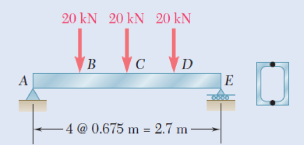
Two metric rolled-steel channels are to be welded along their edges and used to support the loading shown. Knowing that the allowable normal stress for the steel used is 150 MPa, determine the most economical channels that can be used.
Fig. P5.80
Expert Solution & Answer

Trending nowThis is a popular solution!

Students have asked these similar questions
Two rolled-steel channels are to be welded back to back and used to support the loading shown. Knowing that the allowable normal stress for the steel used is 30 ksi, determine the most economical channels that can be used.
Link AB, of width b = 50 mm and thickness t = 6 mm, is used to support the end of a horizontal beam. Knowing that the average normal stress in the link is –140 MPa, and that the average shearing stress in each of the two pins is 80 MPa, determine (a) the diameter d of the pins, (b) the average bearing stress in the link.
A cable AB of span L and a simple beam A'B' of the same span are subjected to identical vertical loadings as shown. Show that the magnitude of the bending moment at a point C' in the beam is equal to the product T0h, where T0 is the magnitude of the horizontal component of the tension force in the cable and h is the vertical distance between point C and the chord joining the points of support A and B.
Chapter 5 Solutions
Loose Leaf For Mechanics Of Materials Format: Looseleaf
Ch. 5.1 - 5.1 through 5.6 For the beam and loading shown,...Ch. 5.1 - 5.1 through 5.6 For the beam and loading shown,...Ch. 5.1 - 5.1 through 5.6 For the beam and loading shown,...Ch. 5.1 - 5.1 through 5.6 For the beam and loading shown,...Ch. 5.1 - 5.1 through 5.6 For the beam and loading shown,...Ch. 5.1 - 5.1 through 5.6 For the beam and loading shown,...Ch. 5.1 - 5.7 and 5.8 Draw the shear and bending-moment...Ch. 5.1 - 5.7 and 5.8 Draw the shear and bending-moment...Ch. 5.1 - 5.9 and 5.10 Draw the shear and bending-moment...Ch. 5.1 - 5.9 and 5.10 Draw the shear and bending-moment...
Ch. 5.1 - 5.11 and 5.12 Draw the shear and bending-moment...Ch. 5.1 - 5.11 and 5.12 Draw the shear and bending-moment...Ch. 5.1 - 5.13 and 5.14 Assuming that the reaction of the...Ch. 5.1 - 5.13 and 5.14 Assuming that the reaction of the...Ch. 5.1 - 5.15 and 5.16 For the beam and loading shown,...Ch. 5.1 - 5.15 and 5.16 For the beam and loading shown,...Ch. 5.1 - For the beam and loading shown, determine the...Ch. 5.1 - For the beam and loading shown, determine the...Ch. 5.1 - 5.19 and 5.20 For the beam and loading shown,...Ch. 5.1 - 5.19 and 5.20 For the beam and loading shown,...Ch. 5.1 - Draw the shear and bending-moment diagrams for the...Ch. 5.1 - 5.22 and 5.23 Draw the shear and bending-moment...Ch. 5.1 - 5.22 and 5.23 Draw the shear and bending-moment...Ch. 5.1 - 5.24 and 5.25 Draw the shear and bending-moment...Ch. 5.1 - 5.24 and 5.25 Draw the shear and bending-moment...Ch. 5.1 - Knowing that W = 12 kN, draw the shear and...Ch. 5.1 - Determine (a) the magnitude of the counterweight W...Ch. 5.1 - Determine (a) the distance a for which the...Ch. 5.1 - Knowing that P = Q = 480 N, determine (a) the...Ch. 5.1 - Solve Prob. 5.29, assuming that P = 480 N and Q =...Ch. 5.1 - Determine (a) the distance a for which the...Ch. 5.1 - A solid steel rod of diameter d is supported as...Ch. 5.1 - A solid steel bar has a square cross section of...Ch. 5.2 - Using the method of Sec. 5.2, solve Prob. 5.1a....Ch. 5.2 - Using the method of Sec. 5.2, solve Prob. 5.2a....Ch. 5.2 - Prob. 36PCh. 5.2 - Prob. 37PCh. 5.2 - Using the method of Sec. 5.2, solve Prob. 5.5a....Ch. 5.2 - Using the method of Sec. 5.2, solve Prob. 5.6a....Ch. 5.2 - Using the method of Sec. 5.2, solve Prob. 5.7. 5.7...Ch. 5.2 - Using the method of Sec. 5.2, solve Prob. 5.8. 5.7...Ch. 5.2 - Prob. 42PCh. 5.2 - Using the method of Sec. 5.2, solve Prob. 5.10....Ch. 5.2 - 5.44 and 5.45 Draw the shear and bending-moment...Ch. 5.2 - 5.44 and 5.45 Draw the shear and bending-moment...Ch. 5.2 - Prob. 46PCh. 5.2 - Prob. 47PCh. 5.2 - Prob. 48PCh. 5.2 - Using the method of Sec. 5.2, solve Prob. 5.20....Ch. 5.2 - 5.50 and 5.51 Determine (a) the equations of the...Ch. 5.2 - 5.50 and 5.51 Determine (a) the equations of the...Ch. 5.2 - 5.52 and 5.53 Determine (a) the equations of the...Ch. 5.2 - 5.52 and 5.53 Determine (a) the equations of the...Ch. 5.2 - 5.54 and 5.55 Draw the shear and bending-moment...Ch. 5.2 - 5.54 and 5.55 Draw the shear and bending-moment...Ch. 5.2 - 5.56 and 5.57 Draw the shear and bending-moment...Ch. 5.2 - 5.56 and 5.57 Draw the shear and bending-moment...Ch. 5.2 - 5.58 and 5.59 Draw the shear and bending-moment...Ch. 5.2 - 5.58 and 5.59 Draw the shear and bending-moment...Ch. 5.2 - Knowing that beam AB is in equilibrium under the...Ch. 5.2 - Knowing that beam AB is in equilibrium under the...Ch. 5.2 - The beam AB supports two concentrated loads P and...Ch. 5.2 - The beam AB supports a uniformly distributed load...Ch. 5.2 - Beam AB supports a uniformly distributed load of 2...Ch. 5.3 - 5.65 and 5.66 For the beam and loading shown,...Ch. 5.3 - 5.65 and 5.66 For the beam and loading shown,...Ch. 5.3 - 5.67 and 5.68 For the beam and loading shown,...Ch. 5.3 - 5.67 and 5.68 For the beam and loading shown,...Ch. 5.3 - 5.69 and 5.70 For the beam and loading shown,...Ch. 5.3 - 5.69 and 5.70 For the beam and loading shown,...Ch. 5.3 - 5.71 and 5.72 Knowing that the allowable normal...Ch. 5.3 - 5.71 and 5.72 Knowing that the allowable normal...Ch. 5.3 - 5.73 and 5.74 Knowing that the allowable normal...Ch. 5.3 - 5.73 and 5.74 Knowing that the allowable normal...Ch. 5.3 - 5.75 and 5.76 Knowing that the allowable normal...Ch. 5.3 - 5.75 and 5.76 Knowing that the allowable normal...Ch. 5.3 - 5.77 and 5.78 Knowing that the allowable normal...Ch. 5.3 - 5.77 and 5.78 Knowing that the allowable normal...Ch. 5.3 - A steel pipe of 100-mm diameter is to support the...Ch. 5.3 - Two metric rolled-steel channels are to be welded...Ch. 5.3 - Two rolled-steel channels are to be welded back to...Ch. 5.3 - Two L4 3 rolled-steel angles are bolted together...Ch. 5.3 - Assuming the upward reaction of the ground to be...Ch. 5.3 - Assuming the upward reaction of the ground to be...Ch. 5.3 - Determine the largest permissible distributed load...Ch. 5.3 - Solve Prob. 5.85, assuming that the cross section...Ch. 5.3 - Determine the largest permissible value of P for...Ch. 5.3 - Solve Prob. 5.87, assuming that the T-shaped beam...Ch. 5.3 - Beams AB, BC, and CD have the cross section shown...Ch. 5.3 - Beams AB, BC, and CD have the cross section shown...Ch. 5.3 - Each of the three rolled-steel beams shown...Ch. 5.3 - A 54-kip load is to be supported at the center of...Ch. 5.3 - A uniformly distributed load of 66 kN/m is to be...Ch. 5.3 - A roof structure consists of plywood and roofing...Ch. 5.3 - Solve Prob. 5.94, assuming that the 6-kN...Ch. 5.3 - Prob. 96PCh. 5.3 - Assuming that the front and rear axle loads remain...Ch. 5.4 - 5.98 through 5.100 (a) Using singularity...Ch. 5.4 - 5.98 through 5.100 (a) Using singularity...Ch. 5.4 - 5.98 through 5.100 (a) Using singularity...Ch. 5.4 - 5.101 through 5.103 (a) Using singularity...Ch. 5.4 - Prob. 102PCh. 5.4 - Prob. 103PCh. 5.4 - Prob. 104PCh. 5.4 - Prob. 105PCh. 5.4 - Prob. 106PCh. 5.4 - Prob. 107PCh. 5.4 - Prob. 108PCh. 5.4 - Prob. 109PCh. 5.4 - Prob. 110PCh. 5.4 - Prob. 111PCh. 5.4 - Prob. 112PCh. 5.4 - 5.112 and 5.113 (a) Using singularity functions,...Ch. 5.4 - Prob. 114PCh. 5.4 - 5.114 and 5.115 A beam is being designed to be...Ch. 5.4 - 5.116 and 5.117 A timber beam is being designed to...Ch. 5.4 - Prob. 117PCh. 5.4 - Prob. 118PCh. 5.4 - Prob. 119PCh. 5.4 - 5.118 through 5.121 Using a computer and step...Ch. 5.4 - Prob. 121PCh. 5.4 - 5.122 and 5.123 For the beam and loading shown and...Ch. 5.4 - 5.122 and 5.123 For the beam and loading shown and...Ch. 5.4 - 5.124 and 5.125 For the beam and loading shown and...Ch. 5.4 - Prob. 125PCh. 5.5 - 5.126 and 5.127 The beam AB, consisting of a...Ch. 5.5 - Prob. 127PCh. 5.5 - 5.128 and 5.129 The beam AB, consisting of a...Ch. 5.5 - 5.128 and 5.129 The beam AB, consisting of a...Ch. 5.5 - Prob. 130PCh. 5.5 - Prob. 131PCh. 5.5 - Prob. 132PCh. 5.5 - 5.132 and 5.133 A preliminary design on the use of...Ch. 5.5 - Prob. 134PCh. 5.5 - Prob. 135PCh. 5.5 - Prob. 136PCh. 5.5 - Prob. 137PCh. 5.5 - Prob. 138PCh. 5.5 - Prob. 139PCh. 5.5 - Assuming that the length and width of the cover...Ch. 5.5 - Two cover plates, each 12 in. thick, are welded to...Ch. 5.5 - Two cover plates, each 12 in. thick, are welded to...Ch. 5.5 - Prob. 143PCh. 5.5 - Prob. 144PCh. 5.5 - Two cover plates, each 7.5 mm thick, are welded to...Ch. 5.5 - Prob. 146PCh. 5.5 - Prob. 147PCh. 5.5 - For the tapered beam shown, determine (a) the...Ch. 5.5 - Prob. 149PCh. 5.5 - Prob. 150PCh. 5.5 - Prob. 151PCh. 5 - Draw the shear and bending-moment diagrams for the...Ch. 5 - Draw the shear and bending-moment diagrams for the...Ch. 5 - Determine (a) the distance a for which the...Ch. 5 - For the beam and loading shown, determine the...Ch. 5 - Draw the shear and bending-moment diagrams for the...Ch. 5 - Beam AB, of length L and square cross section of...Ch. 5 - Prob. 158RPCh. 5 - Knowing that the allowable normal stress for the...Ch. 5 - Prob. 160RPCh. 5 - (a) Using singularity functions, find the...Ch. 5 - Prob. 162RPCh. 5 - Prob. 163RP
Knowledge Booster


Learn more about
Need a deep-dive on the concept behind this application? Look no further. Learn more about this topic, mechanical-engineering and related others by exploring similar questions and additional content below.Similar questions
- Straight rods of 0.30-in. diameter and 200-ft length are sometimes used to clear underground conduits of obstructions or to thread wires through a new conduit. The rods are made of high-strength steel and, for storage and transportation, are wrapped on spools of 5-ft diameter. Assuming that the yield strength is not exceeded, determine (a) the maximum stress in a rod, when the rod, which was initially straight, is wrapped on the spool, (b) the corresponding bending moment in the rod. Use E= 29 * 106 psi.arrow_forwardFor the wide-flange beam with the loading shown, determine the largest load P that can be applied, knowing that the maximum normal stress is 160 MPa and the largest shearing stress is 100 MPa. W360 x 122 Barrow_forwardA solid steel rod of diameter d is supported as shown. Knowing that for steel γ= 490 lb/ft3, determine the smallest diameter d that can be used if the normal stress due to bending is not to exceed 4 ksiarrow_forward
- Knowing that P=Q= 480 N, determine (a) the distance a for which the absolute value of the bending moment in the beam is as small as possible, (b) the corresponding maximum normal stress due to bending.arrow_forwardKnowing that the maximum allowable stress is 41 MPa, determine the magnitude of the largest moment M that can be applied to the component shown. The magnitude of the largest moment M that can be applied to the component is kN·m.arrow_forwardKnowing that for the beam shown the allowable stress is 80 MPa in tension and 100 MPa in compression, determine the largest couple M that can be applied. step by step please!!arrow_forward
- A fabric used in air-inflated structures is subjected to a biaxial loading that results in normal stresses ox = 18 ksi and oz = 24 ksi.Knowing that the properties of the fabric can be approximated as E = 12.6 x 10 psi and v = 0.34, determine the change in length of (a) side AB, (b) side BC, (c) diagonal AC.arrow_forwardAn elastomeric bearing (G=130 psi) is used to support a bridge girder as shown to provide flexibility during earthquakes. The beam must not displace more than 38 in. when a 5-kip lateral load is applied as shown. Knowing that the maximum allowable shearing stress is 60 psi, determine (a) the smallest allowable dimension b, (b) the smallest required thickness a.arrow_forwardHelp me i need solve this _II_ A steel plate 10 mm thick is embedded in a horizontal concrete slab and is used to anchor high strength vertical cable as shown. The diameter of the hole in the plate is 24 mm. the ultimate strength of the steel used is 250 MPa. and the ultimate bonding stress between plate and concrete is 2.1 MPa. Knowing that a factor of safety of 3.60 is desired when P = 18 kN. Determine: a) the required width a of the plate. b) the minimum depth bb to which a plate of that width should be embedded in the concrete slab. (Neglect the normal stresses between the concrete and the lower end of the plate.)arrow_forward
- A standard-weight steel pipe of 12-in. nominal diameter carries water under a pressure of 400 psi. (a) Knowing that the outside diameter is 12.75 in. and the wall thickness is 0.375 in., determine the maximum tensile stress in the pipe. (b) Solve part a, assuming that an extra-strong pipe is used, of 12.75-in. outside diameter and 0.5-in. wall thickness.arrow_forwardEach of the three aluminum bars shown is to be twisted through an angle of 2.1°. Knowing that b = 30 mm, τall = 50 MPa, and G = 27 GPa, determine the shortest allowable length of each bar. Refer to Table 3.1. The shortest allowable length of bar (a) is mm. The shortest allowable length of bar (b) is mm. The shortest allowable length of bar (c) is mm.arrow_forwardDetermine the largest permissible value of P for the beam and loading shown, knowing that the allowable normal stress is +8 ksi in tension and –18 ksi in compression. (Round the final answer to two decimal places.)arrow_forward
arrow_back_ios
SEE MORE QUESTIONS
arrow_forward_ios
Recommended textbooks for you
 Elements Of ElectromagneticsMechanical EngineeringISBN:9780190698614Author:Sadiku, Matthew N. O.Publisher:Oxford University Press
 Mechanics of Materials (10th Edition)Mechanical EngineeringISBN:9780134319650Author:Russell C. HibbelerPublisher:PEARSON
 Thermodynamics: An Engineering ApproachMechanical EngineeringISBN:9781259822674Author:Yunus A. Cengel Dr., Michael A. BolesPublisher:McGraw-Hill Education
 Control Systems EngineeringMechanical EngineeringISBN:9781118170519Author:Norman S. NisePublisher:WILEY
 Mechanics of Materials (MindTap Course List)Mechanical EngineeringISBN:9781337093347Author:Barry J. Goodno, James M. GerePublisher:Cengage Learning
 Engineering Mechanics: StaticsMechanical EngineeringISBN:9781118807330Author:James L. Meriam, L. G. Kraige, J. N. BoltonPublisher:WILEY
Elements Of Electromagnetics
Mechanical Engineering
ISBN:9780190698614
Author:Sadiku, Matthew N. O.
Publisher:Oxford University Press
Mechanics of Materials (10th Edition)
Mechanical Engineering
ISBN:9780134319650
Author:Russell C. Hibbeler
Publisher:PEARSON
Thermodynamics: An Engineering Approach
Mechanical Engineering
ISBN:9781259822674
Author:Yunus A. Cengel Dr., Michael A. Boles
Publisher:McGraw-Hill Education
Control Systems Engineering
Mechanical Engineering
ISBN:9781118170519
Author:Norman S. Nise
Publisher:WILEY
Mechanics of Materials (MindTap Course List)
Mechanical Engineering
ISBN:9781337093347
Author:Barry J. Goodno, James M. Gere
Publisher:Cengage Learning
Engineering Mechanics: Statics
Mechanical Engineering
ISBN:9781118807330
Author:James L. Meriam, L. G. Kraige, J. N. Bolton
Publisher:WILEY
Mechanics of Materials Lecture: Beam Design; Author: UWMC Engineering;https://www.youtube.com/watch?v=-wVs5pvQPm4;License: Standard Youtube License