Concept explainers
Videos
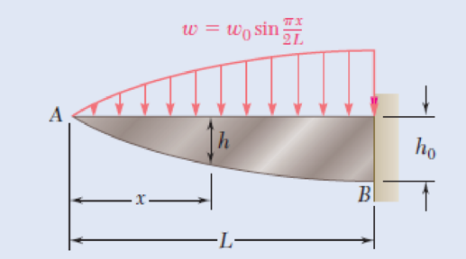
5.128 and 5.129 The beam AB, consisting of a cast-iron plate of uniform thickness b and length L, is to support the distributed load w(x) shown. (a) Knowing that the beam is to be of constant strength, express h in terms of x, L, and h0. (b) Determine the smallest value of h0 if L = 750 mm, b = 30 mm, w0 = 300 kN/m, and σall = 200 MPa.
Fig. P5.129
(a)
Express h in terms of x, L, and
Answer to Problem 129P
The expression for h in terms of x, L, and
Explanation of Solution
Given information:
The uniform thickness of the beam is b.
The length of the beam is L.
The rise of the beam is
Calculation:
By definition;
Substitute
Integrate the equation to find V.
Apply the boundary condition;
Substitute 0 for V and 0 for x in Equation (1).
Substitute
By definition;
Substitute
Apply the boundary condition;
Substitute 0 for M and 0 for x in Equation (2).
Substitute 0 for
Determine the section modulus (S) of the beam using the relation.
Here, the allowable stress in the beam is
Substitute
Determine the section modulus (S) of the rectangular cross section using the relation.
Here, the width of the beam is b and the depth of the beam is h.
Substitute
When
Substitute
Substitute
Therefore, the expression for h in terms of x, L, and
(b)
The smallest value of
Answer to Problem 129P
The smallest value of
Explanation of Solution
Given information:
The maximum allowable stress is
The length of the beam is
The distributed load is
The width of the beam is
Calculation:
Substitute
Therefore, the smallest value of
Want to see more full solutions like this?
Chapter 5 Solutions
Loose Leaf For Mechanics Of Materials Format: Looseleaf


- Knowing that the average normal stress in member CE of the Pratt bridge truss shown must not exceed 21 ksi for the given loading,determine the cross-sectional area of that member that will yield the most economical and safe design. Assume that both ends of the member will be adequately reinforcedarrow_forwardThe center span of the George Washington Bridge, as originally constructed, consisted ol a uniform roadway suspended from four cables. The uniform load supported by each cable was w9.75 kips/ft along the horizontal. Knowing that the span L is 3500 ft and that the sag h is 316 ft, determine for the original configuration (a) the maximum tension in each cable, (b) the length of each cable.arrow_forwardFor the wide-flange beam with the loading shown, determine the largest load P that can be applied, knowing that the maximum normal stress is 160 MPa and the largest shearing stress is 100 MPa. W360 x 122 Barrow_forward
- A large number of uniform and identical cantilever beams, each 1 m long and 146 N / m in weight, are used to support pipes. Consider that the length of the tubes acting under a typical ABCD beam is 1.2 m. And that tubes B and C, plus their contents, weigh 365 N / m and 510 N / m, respectively, determine the reactions at the end set in A, of the cantilever beams.arrow_forwardFive metal strips, each of 0.5 * 1.5-in. cross section, are bonded together to form the composite beam shown. The modulus of elasticity is 30* 106 psi for the steel, 15 *106 psi for the brass, 10 *106 psi for the aluminum. Knowing that the beam is bent about a horizontal axis by a couple of moment 12 kip·in., determine (a) the maximum stress in each of the three metals, (b) the radius of curvature of the composite beam.arrow_forwardKnowing that P= 480 N,Q=320N determine (a) the distance a for which the absolute value of the bending moment in the beam is as small as possible, (b) the corresponding maximum normal stress due to bending.arrow_forward
- A steel bar and an aluminum bar are bonded together to form the composite beam shown. The modulus of elasticity for aluminum is 70 GPa and for steel is 200 GPa. Knowing that the beam is bent about a horizontal axis by a couple of moment M= 1500 N·m, determine the maximum stress in (a) the aluminum, (b) the steel.arrow_forwardThe rectangular tube shown is extruded from an aluminum alloy for which σY= 40 ksi, σU= 60 ksi, and E= 10.6 * 106 psi. Neglecting the effect of fillets, determine (a) the bending moment M for which the factor of safety will be 3.00 and (b) the corresponding radius of curvature of the tubearrow_forwardDetermine the maximum load F that can be applied at the free end of a 3 m cantilever beam of universal rolled-steel beam cross-section, 356 mm deep, with a moment of inertia of 142 × 106 mm4, if the allowable stress is 76 MPa.arrow_forward
- The center span of the Verrazano-Narrows Bridge consists of two uniform roadways suspended from four cables. The design of the bridge allows for the effect of extreme temperature changes that cause the sag of the center span to vary from hw= 386 ft in winter to hs= 394 ft in summer. Knowing that the span is L = 4260 ft, determine the change in length of the cables due to extreme temperature changes.arrow_forwardHelp me i need solve this _II_ A steel plate 10 mm thick is embedded in a horizontal concrete slab and is used to anchor high strength vertical cable as shown. The diameter of the hole in the plate is 24 mm. the ultimate strength of the steel used is 250 MPa. and the ultimate bonding stress between plate and concrete is 2.1 MPa. Knowing that a factor of safety of 3.60 is desired when P = 18 kN. Determine: a) the required width a of the plate. b) the minimum depth bb to which a plate of that width should be embedded in the concrete slab. (Neglect the normal stresses between the concrete and the lower end of the plate.)arrow_forwardA steel pipe and an aluminum pipe are securely bonded together to form the composite beam shown. The modulus of elasticity is 200 GPa for the steel and 70 GPa for the aluminum. Knowing that the composite beam is bent by a couple of moment 500 N?m, determine the maximum stress (a) in the aluminum, (b) in the steel.arrow_forward
 Elements Of ElectromagneticsMechanical EngineeringISBN:9780190698614Author:Sadiku, Matthew N. O.Publisher:Oxford University Press
 Mechanics of Materials (10th Edition)Mechanical EngineeringISBN:9780134319650Author:Russell C. HibbelerPublisher:PEARSON
 Thermodynamics: An Engineering ApproachMechanical EngineeringISBN:9781259822674Author:Yunus A. Cengel Dr., Michael A. BolesPublisher:McGraw-Hill Education
 Control Systems EngineeringMechanical EngineeringISBN:9781118170519Author:Norman S. NisePublisher:WILEY
 Mechanics of Materials (MindTap Course List)Mechanical EngineeringISBN:9781337093347Author:Barry J. Goodno, James M. GerePublisher:Cengage Learning
 Engineering Mechanics: StaticsMechanical EngineeringISBN:9781118807330Author:James L. Meriam, L. G. Kraige, J. N. BoltonPublisher:WILEY