Engineering Mechanics: Statics - With Access (Custom)
14th Edition
ISBN: 9781323462942
Author: HIBBELER
Publisher: PEARSON
expand_more
expand_more
format_list_bulleted
Concept explainers
Videos
Textbook Question
Chapter 5.4, Problem 24P
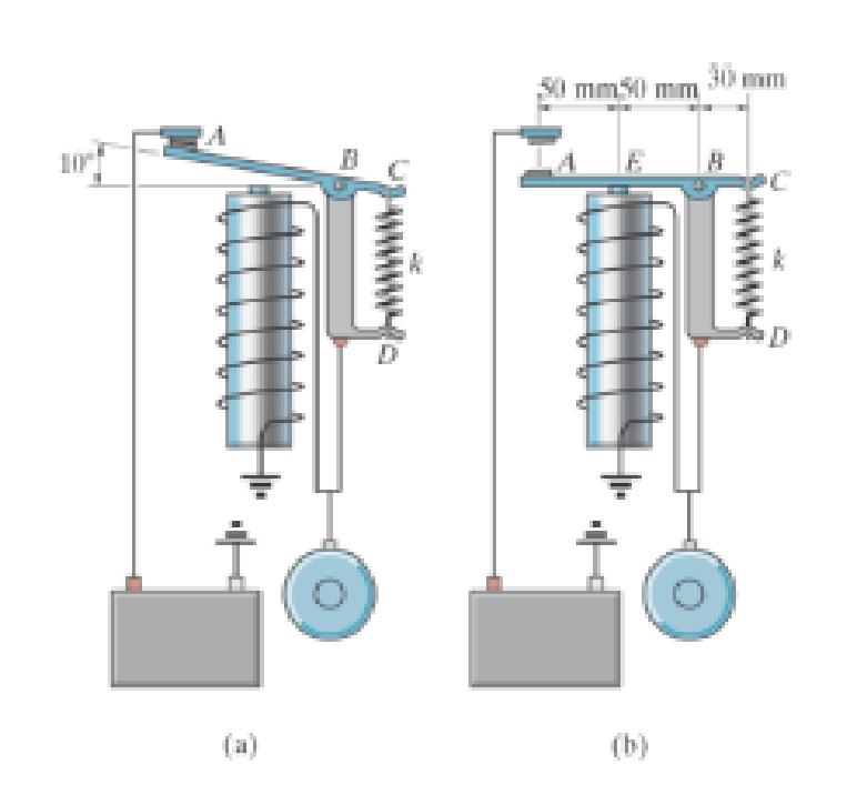
The relay regulates voltage and current. Determine the force at the spring CD, which has a stiffness or k = 120 N/m, so that it will allow the armature to make contact at A in figure (a) with a vertical force of 0.4 N. Also, determine the force in the spring when the cot is energized and attracts the armature to E, figure (b), thereby breaking contact at A.
Expert Solution & Answer
Want to see the full answer?
Check out a sample textbook solution
Students have asked these similar questions
The figure shows a control bar, subjected to a force of 90N. Since the length of the bar is 225 mm and the moment of the clockwise force on B is 13.5 N.m, determine the value of α. Solve the problem using scalar notation and explain your result.
Select the distance a between 2 m and 5 m and the force P between 15 kN and 35 kN in the cage system shown in the figure and find the rod forces. Also note that the forces on the rods did not compress my tension. (AE, AB, BE, DE, CD, BC, BD =?)
Find the internal force system acting on section 3 for the pin-connected frame.
a P = 255 N (C), V = 0, M = 29.8 N · m
b P = 255 N (T), V = 0, M = 29.8 N · m
c P = 255 N (C), V = 0, M = 92.8 N · m
d P = 525 N (C), V = 0, M = 29.8 N · m
Chapter 5 Solutions
Engineering Mechanics: Statics - With Access (Custom)
Ch. 5.2 - Draw the free-body diagram for the following...Ch. 5.2 - Draw the free-body diagram for the following...Ch. 5.2 - Draw the free-body diagram for the following...Ch. 5.2 - Draw the free-body diagram for the following...Ch. 5.2 - Draw the free-body diagram for the following...Ch. 5.2 - Draw the free-body diagram for the following...Ch. 5.2 - Draw the free-body diagram for the following...Ch. 5.2 - Draw the free-body diagram for the following...Ch. 5.2 - Draw the free-body diagram for the following...Ch. 5.4 - Draw the free body diagram of each object. Prob....
Ch. 5.4 - Determine the horizontal and vertical components...Ch. 5.4 - Determine the horizontal and vertical components...Ch. 5.4 - The truss is supported by a pin at A and a roller...Ch. 5.4 - Determine the components of reaction at the fixed...Ch. 5.4 - The 25 kg bar has a center of mass at G. If it is...Ch. 5.4 - Determine the reactions at the smooth contact...Ch. 5.4 - Determine the components of the support reactions...Ch. 5.4 - Determine the reactions at the supports. Prob....Ch. 5.4 - Determine the horizontal and vertical components...Ch. 5.4 - Determine the reactions at the supports. Prob....Ch. 5.4 - Determine the reactions at the supports. Prob....Ch. 5.4 - Determine the reactions at the supports. Prob....Ch. 5.4 - Determine the tension in the cable and the...Ch. 5.4 - The man attempts to a up port the toad of boards...Ch. 5.4 - Determine the components of reaction at the...Ch. 5.4 - The man has a weight W and stands at the center of...Ch. 5.4 - A uniform glass rod having a length L is placed in...Ch. 5.4 - The uniform rod AB has a mass of 40 kg. Determine...Ch. 5.4 - If the intensity of the distributed load acting on...Ch. 5.4 - If the roller at A and the pin at B can support a...Ch. 5.4 - The relay regulates voltage and current. Determine...Ch. 5.4 - Determine the reactions on the bent rod which is...Ch. 5.4 - The mobile crane is symmetrically supported by two...Ch. 5.4 - Determine the reactions acting on the smooth...Ch. 5.4 - A linear torsional spring deforms such that an...Ch. 5.4 - Determine the force P needed to pull the 50-kg...Ch. 5.4 - Determine the magnitude and direction of the...Ch. 5.4 - The operation of the fuel pump for an automobile...Ch. 5.4 - Determine the magnitude of force at the pin A and...Ch. 5.4 - The dimensions of a jib crane, which is...Ch. 5.4 - The dimensions of a jib crane, which is...Ch. 5.4 - The smooth pipe rests against the opening at the...Ch. 5.4 - The beam of negligible weight is supported...Ch. 5.4 - The cantilevered jib crane is used to support the...Ch. 5.4 - The cantilevered jib crane is used to support the...Ch. 5.4 - The bar of negligible weight is supported by two...Ch. 5.4 - Determine the stiffness k of each spring so that...Ch. 5.4 - The bulk head AD Is subjected to both water and...Ch. 5.4 - The boom supports the two vertical loads. Neglect...Ch. 5.4 - The boom is intended to support two vertical loads...Ch. 5.4 - The 10-kg uniform rod is pinned at end A. If It is...Ch. 5.4 - If the truck and its contents have a mass of 50 kg...Ch. 5.4 - Three uniform books each having a weight W and...Ch. 5.4 - Determine the reactions at the pin A and the...Ch. 5.4 - If rope BC will fail when the tension becomes 50...Ch. 5.4 - The rigid metal strip of negligible weight is used...Ch. 5.4 - The rigid metal strip of negligible weight is used...Ch. 5.4 - The cantilever footing is used to support a wail...Ch. 5.4 - The uniform beam has a weight Wand length l and is...Ch. 5.4 - A boy stands out at the end of the diving board,...Ch. 5.4 - The 30-N uniform rod has a length of l = 1 m. If s...Ch. 5.4 - The uniform rod has a length I and weight W. It is...Ch. 5.4 - I he uniform rod of length L and weight W is...Ch. 5.4 - Assuming that the foundation exerts a linearly...Ch. 5.4 - Assuming that the foundation exerts a linearly...Ch. 5.4 - If it is also subjected to a couple moment of 100...Ch. 5.4 - Determine the distance d for placement of the load...Ch. 5.4 - If d = 1 m, and = 30, determine me normal...Ch. 5.4 - The man attempts to pull the tour wheeler up the...Ch. 5.4 - Where is the best place to arrange most of the...Ch. 5.7 - Draw the free-body diagram of each object.Ch. 5.7 - In each case, write the moment equations about the...Ch. 5.7 - The uniform plate has a weight of 500 lb....Ch. 5.7 - Determine the reactions at the roller support A,...Ch. 5.7 - The rod is supported by smooth journal bearings at...Ch. 5.7 - Determine the support reactions at the smooth...Ch. 5.7 - Determine the force developed in the short link...Ch. 5.7 - Determine the components of reaction that the...Ch. 5.7 - Determine the tension each rope and the force that...Ch. 5.7 - If these components have weights WA = 45000 Wa =...Ch. 5.7 - Determine the components of reaction at the fixed...Ch. 5.7 - Determine the vertical reactions at the wheels C...Ch. 5.7 - Determine the components of reaction at A, the...Ch. 5.7 - Determine the tension in each of the three...Ch. 5.7 - Determine the components of reaction at hinges A...Ch. 5.7 - Determine me tension in each cable and the...Ch. 5.7 - The cables are attached to a smooth collar ring at...Ch. 5.7 - Determine the components of reaction at the...Ch. 5.7 - Determine the components of reaction at the...Ch. 5.7 - Determine the components of reaction at the...Ch. 5.7 - Determine the magnitude of F which will cause the...Ch. 5.7 - Determine the components of reaction at A and the...Ch. 5.7 - Determine the components of reaction at these...Ch. 5.7 - Determine the components or reaction at these...Ch. 5.7 - Compute the x, y, z components of reaction at the...Ch. 5.7 - Determine the magnitude of F2 which will cause the...Ch. 5.7 - At A the connection is with a ball-and-socket....Ch. 5.7 - If it is supported by a ball-and-socket joint at C...Ch. 5.7 - Determine the x, y, z components of reaction at...Ch. 5.7 - Determine the horizontal tension T in the belt on...Ch. 5.7 - Determine the horizontal tension T in the belt on...Ch. 5.7 - Determine the components of reaction at A and the...Ch. 5.7 - If the roller at 8 can sustain a maximum load of 3...Ch. 5.7 - Determine the reactions at the supports A and B...Ch. 5.7 - Determine the normal reaction at the roller A and...Ch. 5.7 - Determine the horizontal and vertical components...Ch. 5.7 - Determine the x, y, z components of reaction at...Ch. 5.7 - Determine the horizontal equilibrium force P that...Ch. 5.7 - Determine the x, y, z components of reaction at...Ch. 5.7 - Determine the x and z components of reaction at...
Knowledge Booster


Learn more about
Need a deep-dive on the concept behind this application? Look no further. Learn more about this topic, mechanical-engineering and related others by exploring similar questions and additional content below.Similar questions
- A spring with a constant equal to 15 KN/m is connected to points C and F of the mechanism shown in the figure. Neglecting the weight of the spring and the mechanism, determine the force on the spring and the vertical displacement of point G when a force 120 N vertical, directed downward, applies a) at point Farrow_forwardIn the simple cage system in the figure, which of the following is the absolute value of the force carried by the CE element in kN?arrow_forwardThe system in the Figure is in equilibrium. A mass M1 = 246.0 kg hangs from the end of a uniform strut which is held at an angle theta = 40.0o with respect to the horizontal. The cable supporting the strut is at angle alpha = 24.4o with respect to the horizontal. The strut has a mass of 58.2 kg. Find the magnitude of the tension T in the cable. Find the magnitude of the horizontal component of the force exerted on the strut by the hinge? Find the magnitude of the vertical component of the force exerted on the strut by the hinge?arrow_forward
- The curved gate in Figure 3 is a 90º arc and is pivoted at O. It has a uniformly distributed mass of mL = 25 kg/m. Obtain a) the magnitude of the force per unit length FL to keep the gate closed and b) the components of the reaction at the hinge at point O for the case that the gate is L = 8.0 m longarrow_forwardFind the support reacions and joint force of the construction shown on the figure, if; P=12 kN q=9 kN/m M=12 kN and L=2 marrow_forwardA spring with a constant equal to 15 KN/m is connected to points C and F of the mechanism shown in the figure. Neglecting the weight of the spring and the mechanism, determine the force on the spring and the vertical displacement of point G when a force vertical 120 vertical, directed downward, is applied a) at point F and b) at points F and Darrow_forward
- in the system shown, the bar AB can withstand a tension of 4.90 kN, and a compression of 2.53 kN; the spring constant k is 2.85 kN / m, the spring's undeformed length is 0.433 m, the mass of W is 365 kg, and the force P makes an angle of 60 ° with the horizontal. Calculate the stretched length of the spring and the magnitude of the force P so that:- The bar fails due to tension- The bar fails due to compression NOTE 1: For the direction of the force P do not be guided by the drawing. The force P can point in any direction (all 4 quadrants) as long as it maintains the indicated angle with respect to the horizontal.arrow_forwardTwo gondolas on a ski lift are locked in the postion show in the figure while repairs are being made elsewhere.The distance between support towers is L = LOO ft.The length of each cable segement under gondolas weighing WB= 450 lb and Wc=650 lb are DAB=12 ft, DBC=70 a , and DCB=20 ft . The cable sag at B is AB = 3.9 ft and that C is A = 7.1 ft.THe effective cross-sectional area of the cables is Ae=0.12 in". (a) Find the tension force in each segment; neglect the mass of the cable. (b) Find the average stress(σ) in each cable segment.arrow_forwardFind the support reactions and joint force of the construction,shown on the figure ,if P=12 kN q=9 kN/m , M= 12 kN , and L=2marrow_forward
- For two existing torques, what third force at a given distance from the pivot will balance them? Imagine a meter stick set up as in the figure. It hangs from a central bracket, and two hanging masses can hang from it from each of their brackets. At a third location, a force probe can either pull up or pull down on the stick, depending on what is needed to balance the stick. The mass of the meter stick is 120 g. sketch the situation (drawing r1, r2, r3, F1, F2, and F3) and determine the magnitude (value) and direction (+ or -) of each torque. Don't include the mass of a bracket that would hold the hanging mass in place; assume the mass listed is the entire mass hanging at that point. For each trial, use the principle of equilibrium (where the sum of torques is zero) to calculate the third, unknown force acting at x3arrow_forward3- F1, +y in the –z direction to the bent AEB pipe in the figure. F2 forces are applied in the direction of One from end of pipe A supported by a ball joint; also BD and BC balanced with cables. Accordingly, the BD cable Calculate the strength of the force. F1=(9)kN, F2 =10kN, h = (6)marrow_forwardThe mass in the figure is in balance with an AC cable and arc AB as in the figure. If the spring coefficient is k=1000 N/m and the unstressed length of the spring is 660 mm, which of the following is the force in the AD cable in kN for the position shown?arrow_forward
arrow_back_ios
SEE MORE QUESTIONS
arrow_forward_ios
Recommended textbooks for you
 Elements Of ElectromagneticsMechanical EngineeringISBN:9780190698614Author:Sadiku, Matthew N. O.Publisher:Oxford University Press
 Mechanics of Materials (10th Edition)Mechanical EngineeringISBN:9780134319650Author:Russell C. HibbelerPublisher:PEARSON
 Thermodynamics: An Engineering ApproachMechanical EngineeringISBN:9781259822674Author:Yunus A. Cengel Dr., Michael A. BolesPublisher:McGraw-Hill Education
 Control Systems EngineeringMechanical EngineeringISBN:9781118170519Author:Norman S. NisePublisher:WILEY
 Mechanics of Materials (MindTap Course List)Mechanical EngineeringISBN:9781337093347Author:Barry J. Goodno, James M. GerePublisher:Cengage Learning
 Engineering Mechanics: StaticsMechanical EngineeringISBN:9781118807330Author:James L. Meriam, L. G. Kraige, J. N. BoltonPublisher:WILEY
Elements Of Electromagnetics
Mechanical Engineering
ISBN:9780190698614
Author:Sadiku, Matthew N. O.
Publisher:Oxford University Press
Mechanics of Materials (10th Edition)
Mechanical Engineering
ISBN:9780134319650
Author:Russell C. Hibbeler
Publisher:PEARSON
Thermodynamics: An Engineering Approach
Mechanical Engineering
ISBN:9781259822674
Author:Yunus A. Cengel Dr., Michael A. Boles
Publisher:McGraw-Hill Education
Control Systems Engineering
Mechanical Engineering
ISBN:9781118170519
Author:Norman S. Nise
Publisher:WILEY
Mechanics of Materials (MindTap Course List)
Mechanical Engineering
ISBN:9781337093347
Author:Barry J. Goodno, James M. Gere
Publisher:Cengage Learning
Engineering Mechanics: Statics
Mechanical Engineering
ISBN:9781118807330
Author:James L. Meriam, L. G. Kraige, J. N. Bolton
Publisher:WILEY
Column buckling; Author: Amber Book;https://www.youtube.com/watch?v=AvvaCi_Nn94;License: Standard Youtube License