Videos
The cantilever footing is used to support a wail near its edge A so that it causes a uniform soil pressure under the footing. Determine the uniform distribution loads. WA and WB, measured in lb/ft at pads A and B1 necessary to support the wall forces of 8000 lb and 20 000 lb.
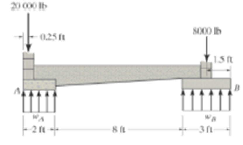
Prob. 5-51

Learn your wayIncludes step-by-step video

Chapter 5 Solutions
Engineering Mechanics: Statics, Student Value Edition; Modified Mastering Engineering with Pearson eText -- Standalone Access Card -- for Engineering Mechanics: Statics (14th Edition)
Additional Engineering Textbook Solutions
Applied Fluid Mechanics (7th Edition)
Engineering Mechanics: Dynamics (14th Edition)
Engineering Mechanics: Statics
Statics and Mechanics of Materials (5th Edition)
Applied Statics and Strength of Materials (6th Edition)
Automotive Technology: Principles, Diagnosis, and Service (5th Edition)


- The rigid bar is supported by the two short white spruce wooden posts and a spring. If each of the posts has an unloaded length of 1 m and a cross-sectional area of 600 mm2, and the spring has a stiffness of k = 2 MN >m and an unstretched length of 1.02 m, determine the force in each post after the load is applied to the bar.arrow_forwardThe sign has a mass of 150kg with center of mass in G. Draw the free body diagram and determine the components along x,y,z of the reaction in ball joint A as well as the tensile strength in wires BC and BD(Caution : they are two different wires). g=9.81m/s²arrow_forwardThe mobile crane is symmetrically supported by two outriggers at A and B to relieve the suspension of the vehicle on which it sits and to provide extra stability. Determine the vertical reactions at each of the two outriggers as a function of boom angle when the boom is carrying a 1.2 Mg load and the crane and truck have a combined mass of 18 Mg and the boom has a mass of 2 Mg. 0 = 45°arrow_forward
- Find the minimum force P required for impending motion of the block up the inclined surface, given: Mblock = 65 kg, θ = 52 °, μ = 0.4arrow_forwardThe disk B has a mass of 20 kg and is supported on the smooth cylindrical surface by a spring with stiffness k= 400 N/m and unstretched length l0= 1 m. The spring remains in the horizontal position since its end A is attached to the small roller guide which has negligible weight. Determine the equilibrium angle of the roller.arrow_forwardIf cylinder E has a mass of 20 kg and each cable segment can sustain a maximum tension of 400 N, determine the following: 3.1 The largest mass of cylinder F that can be supported by the system is ______ kg. 3.2 The sag yC is equal to ______ m.arrow_forward
- The cylinder has a mass of 30 kg and is mounted on an axle that is supported by bearings at A and B. If the axle is turning at 40 rad/s (direction see figure) determine the vertical components of force acting at the bearings at this instantarrow_forwardThe ends of the three cables are attached to a ring at A and to the edge of the uniform plate. Determine the largest mass the plate can have if each cable can support a maximum tension of 15 kN.arrow_forwardThe A-36 steel wires AB and AD each have a diameter of 2 mm and the unloaded lengths of each wire are LAC = 1.60 m and LAB = LAD = 2.00 m. Determine the required diameter of wire AC so that each wire is subjectedto the same force when the 150-kg mass is suspended from the ring at A.arrow_forward
- SHOW THE FREE BODY DIAGRAMarrow_forwardThe assembly consists two different sections with diameter of 40 mm and 20 mm, respectively. If the gap between C and the rigid wall at D is initially 0.2 mm, determine the support reactions at A and D when the force P = 150 kN is applied. The assembly is made of solid steel cylinders with elastic modulus of 200 GPa.arrow_forwardThe bracket is held to the wall using three A-36 steel bolts at B, C, and D. Each bolt has a diameter of 0.5 in. and an unstretched length of 2 in. If a force of 800 lb is placed on the bracket as shown, determine the force developed in each bolt. For the calculation, assume that the bolts carry no shear; rather, the vertical force of 800 lb is supported by the toe at A. Also, assume that the wall and bracket are rigid. A greatly exaggerated deformation of the bolts is shown.arrow_forward
 Elements Of ElectromagneticsMechanical EngineeringISBN:9780190698614Author:Sadiku, Matthew N. O.Publisher:Oxford University Press
 Mechanics of Materials (10th Edition)Mechanical EngineeringISBN:9780134319650Author:Russell C. HibbelerPublisher:PEARSON
 Thermodynamics: An Engineering ApproachMechanical EngineeringISBN:9781259822674Author:Yunus A. Cengel Dr., Michael A. BolesPublisher:McGraw-Hill Education
 Control Systems EngineeringMechanical EngineeringISBN:9781118170519Author:Norman S. NisePublisher:WILEY
 Mechanics of Materials (MindTap Course List)Mechanical EngineeringISBN:9781337093347Author:Barry J. Goodno, James M. GerePublisher:Cengage Learning
 Engineering Mechanics: StaticsMechanical EngineeringISBN:9781118807330Author:James L. Meriam, L. G. Kraige, J. N. BoltonPublisher:WILEY