
Concept explainers
Videos
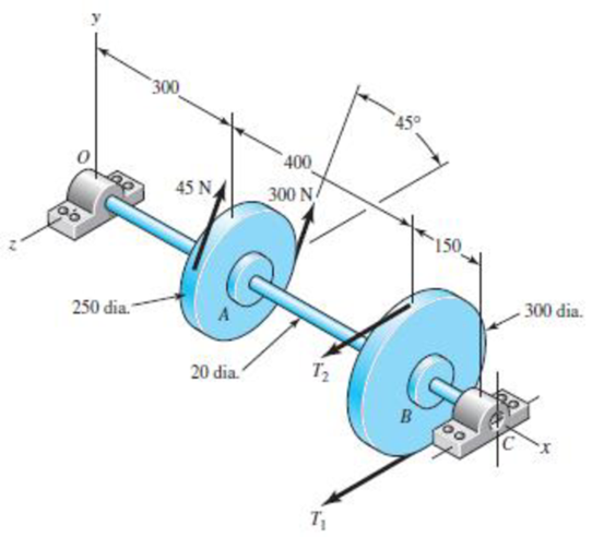
For the problem specified in the table, build upon the results of the original problem to determine the minimum factor of safety for fatigue based on infinite life, using the modified Goodman criterion. The shaft rotates at a constant speed, has a constant diameter, and is made from cold-drawn AISI 1018 steel.
The minimum factor of safety for fatigue on infinite life, using the modified Goodman criterion.
Answer to Problem 40P
The minimum factor of safety for fatigue on infinite life is
Explanation of Solution
Write the relationship between tensions on the loose side with respect to tension on the tight side.
Here, the tension on the tight side is
Write the expression to balance the tension on the counter shaft.
Here, the tension on the tight side of pulley
Substitute
Write the expression for the magnitude of bearing reaction force at
Here, the magnitude of the bearing force at
Write the expression for the magnitude of bearing reaction force at
Here, the magnitude of bearing reaction force at
Write the expression for the magnitude of bearing reaction force at
Here, the magnitude of bearing force at
Write the expression for the magnitude of bearing force at
Here, the magnitude of bearing reaction force at
Write the expression for the bearing reaction force at
Here, the bearing reaction force at
Write the expression for the bearing reaction force at
Here, the bearing reaction force at
Write the expression for the moment at
Here, the moment at
Write the expression for the moment at
Here, the moment at
It is clear from the bending moment diagram, that the critical location is at
Write the expression for the net moment at point
Here, the net moment at
Write expression for the torque transmitted by shaft from
Here, the torque transmitted by shaft from
Write the expression for the bending stress.
Here, the bending stress is
Write the expression for the shear stress.
Here, the shear stress is
Write the expression for von Misses stress for alternating
Here, alternating stress due to completely reversed is
Write the expression for von Misses stress for mid-range.
Here, mean stress due to completely reversed is
Write the expression for von Mises for maximum stress.
Write the expression for yielding by using distortion energy theory.
Here the
Write the expression for endurance limit of rotary test specimen.
Write the expression for surface condition modification factor.
Write the expression for size modification factor.
Write the expression for modified endurance limit.
Write the expression to find out factor of safety by using modified Goodman.
Here modified endurance limit is
Conclusion:
Substitute
Substitute
Substitute
Substitute
Substitute
Substitute
Substitute
Substitute
Substitute
Substitute
Substitute
Substitute
Convert diameter of shaft from millimeter to meter.
Substitute
Substitute
Substitute
Substitute
Substitute
Refer to Table A-20 “Deterministic ASTM tensile and yield strengths for some hot-rolled (HR) and cold-drawn (CD) steels” to obtain the yield strength for AISI 1018 CD steel as
Substitute
Refer to Table A-20 “Deterministic ASTM tensile and yield strengths for some hot-rolled (HR) and cold-drawn (CD) steels” to obtain the ultimate strength for AISI 1018 CD steel as
Substitute
Substitute
Substitute
Substitute
Substitute
Thus minimum factor of safety by using modified Goodman criterion is
Want to see more full solutions like this?
Chapter 6 Solutions
Shigley's Mechanical Engineering Design (McGraw-Hill Series in Mechanical Engineering)


- A bracket is under a loading condition shown below. It's made from a steel with yield strength (Sy) of 42 ksi and ultimate tensile strength (Sut) of 76 ksi. The diameter is 0.42 in and b = 1.75 in, with the load P fluctuate between 15 lbs (tension) and -5 lbs (compression). Using the modified Goodman or Gerber criterion, determine the fatigue factor of safety based on infinite life. If infinite life is not predicted, estimate the number of cycles to failure. Also check for yielding.arrow_forwardA certain steel shafting material has an ultimate strength of 93 ksi, a notch radius of 0.25 inch, and a stress concentration factor of 2.5 at its pitch. Determine the fatigue-strength reduction factor for a life of 166,077 cycles onlyarrow_forwardA 1-in-diameter solid round bar has a groove 0.1-in deep with a 0.1-in radius machined into it. The bar is made of AISI 1020 CD steel and is subjected to a purely reversing torque of 1800 lb-in. For the S-N diagram of this material, let f=0.9. Estimate the number of cycles to failure. If the bar is also placed in an environment with a temperature of 750 F, estimate the number of cycles to failurearrow_forward
- Two steels are being considered for manufacture of as-forged connecting rods subjected to bending loads. One is AISI 4340 Cr-Mo-Ni steel capable of being heat-treated to a tensile strength of 260 ksi. The other is a plain carbon steel AISI 1040 with a ultimate strength of 113 ksi. Each rod is to have a size giving an equivalent diameter of 0.75 in. Determine the endurance limit for each material. Is there any advantage to using the alloy steel for this fatigue application?arrow_forwardA strain gauge mounted at a potentially critical point in a steel part has recorded the stress history shown below during 20 seconds of typical use. Identical parts have been fatigue tested under constant amplitude loading with R = -1 to give an endurance limit of 60 ksi and a fatigue strength of 140 ksi at N = 1000 cycles. The steel used has an ultimate strength of 165 ksi. Estimate the fatigue life of the part under typical use. How much will the fatigue life in problem 3 (above) be reduced if a mean stress of 10 ksi is added to the stress history given?arrow_forwardA round cross section cold drawn steel bar made of AISI 1020 has adiameter of 35 mm. Based on a conservative failure analysis, calculate factorof safety in the following conditions:a) The bar is subjected to static bending moment of 450 N.m, and steadytorque of 180 N.mb) The bar is subjected to bending moment fluctuating between(900 N.m and 400 N.m), and steady tension of 2.4 kNarrow_forward
- A rectangular bar is cut from an AISI 1018 cold-drawn steel flat. The bar is 1 in wide by 3/8 in thick and has a ¼ in-diameter hole drilled through the center. The bar is subjected to a tension load fluctuating between 800 and 3000 lb. estimate the factors of safety guarding against failure by yielding and by fatigue action. (Assume infinite life is desire)arrow_forwardAn input shaft of a gearbox with motor power P = 7 kW and rotation number n = 1300 rpm. The diameter of an input shaft is d = 20 mm and its material is 16MnCr5. A force of F = 2800 N forces the shaft due to the operation of a gear wheel connected with a wedge on the input shaft. The distances of the gear from the bearings are given as L₁ = 40 mm and L2 = 60 mm. In the most dangerous section, you are required to check the strength according to the S = 3 safety factor. If the section is unsafe in terms of strength, what changes would you make in the design to make it safe? (The surface of the spindle is machined as fine chips, reliability poor Kg = 1.).arrow_forwardA 4340 quench and tempered rotating steel shaft, d = 1 in, is loaded in fully reversed bending . The bar has been machined with surface conditions a = 1.34 ksi and b = -0.085, and will be operating at room temperature. The program requires a reliability of 99.99 percent. The fillet radii at all points is r = 0.08 in. The fatigue strength fraction f = 0.76, and the The ultimate strength (Sut) is 260 Ksi. Determine the endurance limit in the aforementioned conditionsarrow_forward
- The shaft below is an engine component that is rotating. It is machined from an unknown ductile material with a measured ultimate tensile strength of 700 MPa. Answer the questions below assuming a desired reliability of 99% and a fatigue fraction, f, of 0.9. Round all values and answers to 2 decimal places Determine the maximum stress in the shaft due to the applied loading (hint: what is the maximum moment?) Estimate the endurance limit (hint: what is the relationship between Se and Sut and don’t forget any necessary modifying factors.) Determine the number of cycles to failure.arrow_forwardAn alloy steel Metric 10x1.5 screw (10 mm diameter, pitch p = 1.5 mm) is to be turned into a threaded hole and tightened to one/half of its proof strength. According to Table 30.2, the proof strength = 830 MPa. Determine the maximum torque that should be used if the torque coefficient = 0.18arrow_forwardProduced from xCy steel material by machining method, the shaft is bedded at C and D points. With the shaft, constant Fy= 830 N forces in the vertical direction and constant Fx= 4,3 kN forces in the axial direction, which do not rotate together. The tensile strength of the shaft material is (sigma)tensile = 630 MPa and the yield strength is (sigma)yield = 430 MPa. For 50% reliability, analyze the fatigue damage condition of the shaft sections A and B separately.Question: How do we apply a tensile force to a part supported on both sides?Answer: We think that one of the bearings is a bearing that allows axial movement.(Take SI unit and make the solutions legit and clear please. I need an answer even though it doesn't reach a clear solution.)arrow_forward
 Elements Of ElectromagneticsMechanical EngineeringISBN:9780190698614Author:Sadiku, Matthew N. O.Publisher:Oxford University Press
 Mechanics of Materials (10th Edition)Mechanical EngineeringISBN:9780134319650Author:Russell C. HibbelerPublisher:PEARSON
 Thermodynamics: An Engineering ApproachMechanical EngineeringISBN:9781259822674Author:Yunus A. Cengel Dr., Michael A. BolesPublisher:McGraw-Hill Education
 Control Systems EngineeringMechanical EngineeringISBN:9781118170519Author:Norman S. NisePublisher:WILEY
 Mechanics of Materials (MindTap Course List)Mechanical EngineeringISBN:9781337093347Author:Barry J. Goodno, James M. GerePublisher:Cengage Learning
 Engineering Mechanics: StaticsMechanical EngineeringISBN:9781118807330Author:James L. Meriam, L. G. Kraige, J. N. BoltonPublisher:WILEY