
Concept explainers
Videos
6-37* to 6-46* For the problem specified in the table, build upon the results of the original problem to determine the minimum factor of safety for fatigue based on infinite life, using the modified Goodman criterion. The shaft rotates at a constant speed, has a constant diameter, and is made from cold-drawn AISI 1018 steel.
| Problem Number | Original Problem, Page Number |
| 6-43* | 3–74, 152 |
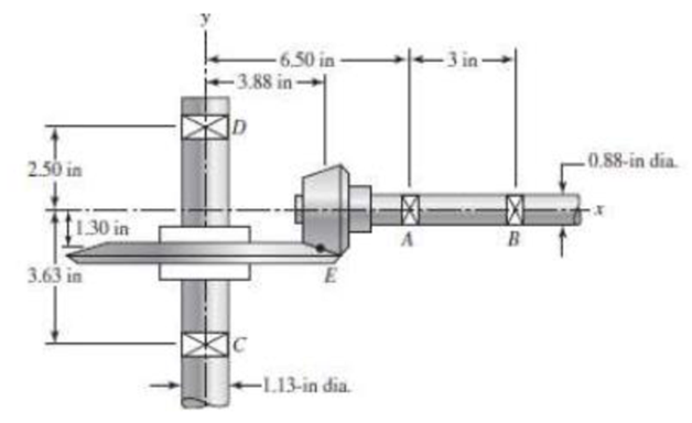
3-74* In the figure, shaft AB transmits power to shaft CD through a set of bevel gears contacting at point E. The contact force at E on the gear of shaft CD is determined to be (FE)CD = –92.8i – 362.8j + 808.0k lbf. For shaft CD: (a) draw a free-body diagram and determine the reactions at C and D assuming simple supports (assume also that bearing C carries the thrust load), (b) draw the shear-force and bending-moment diagrams, (c) for the critical stress element, determine the torsional shear stress, the bending stress, and the axial stress, and (d) for the critical stress element, determine the principal stresses and the maximum shear stress.
The minimum factor of safety for fatigue based on infinite life.
Answer to Problem 43P
The minimum factor of safety for fatigue based on infinite life is
Explanation of Solution
The free body diagram of the arrangement of shafts is shown in the figure below.
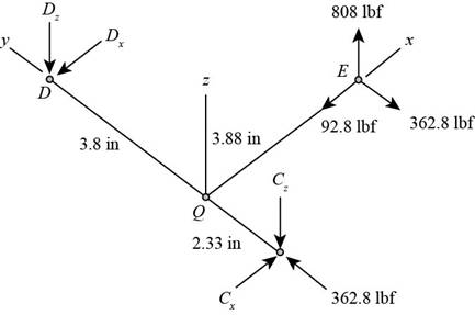
Figure (1)
Write the expression of moment at
Here, the reaction at
Write the expression of moment at
Here, the reaction at
Write the expression of moment at
Here, the reaction at
Write the expression of moment at
Write the expression of net force at
Here, the reaction at
It is clear from the free body diagram of the shaft
The calculations for shear force diagram in
Write the expression of Shear force at
Here, the shear at
Write the expression of Shear force at
Here, the shear force at
Write the expression of Shear force at
Here, the shear force at
The calculations for bending moment diagram in
We known that, the bending moment at the supports of the simply supported beam is zero.
Write the bending moment at
Here, the bending moment at
Write the expression of bending moment at
Here, the bending moment at
Write the expression of bending moment at
Here, the bending moment at
The calculations for shear force diagram in
Write the expression of Shear force at
Here, the shear at
Write the expression of Shear force at
Here, the shear force at
Write the expression of Shear force at
Here, the shear force at
We known that, the bending moment at the supports of the simply supported beam is zero.
Write the bending moment at
Here, the bending moment at
Write the expression of bending moment at
Here, the bending moment at
It is clear from the bending moment diagram that the critical stress element is located at just right of
Write the expression of maximum torque acting on the shaft
Here, the maximum torque acting on the shaft
Write the expression of maximum bending moment acting on the shaft
Here, the maximum bending moment acting on the shaft
Write the expression of torsional shear stress for critical stress element.
Here, the torsional shear stress for critical stress element is
Write the expression of bending stress for critical stress element.
Here, the bending stress for critical stress element is
Write the expression of axial stress for critical stress element.
Here, the axial stress for critical stress element is
Write the expression for von Mises alternating stress.
Here, the amplitude component of the axial stress is
Write the expression for von Mises mid-range stress.
Here, the mid-range component of the axial stress is
Write the expression for von Mises maximum stress.
Here, the maximum component of the axial stress is
Write the expression for yield factor of safety.
Here, the yield strength of the material is
Write the expression for endurance limit for test specimen.
Here, the minimum tensile strength is
Write the surface factor for the countershaft.
Here, the constants for surface factor are
Write the size factor for the countershaft.
Write the endurance limit at the critical location of the machine part.
Write the modified Goodman equation.
Here, the fatigue factor of safety is
Conclusion:
Substitute
Substitute
Substitute
Substitute
Substitute
Substitute
Substitute
Substitute
Substitute
Substitute
The figure below shows the shear force and bending moment diagram in
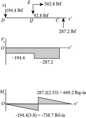
Figure-(2)
Substitute
Substitute
Substitute
Substitute
The figure below shows the shear force and bending moment diagram in
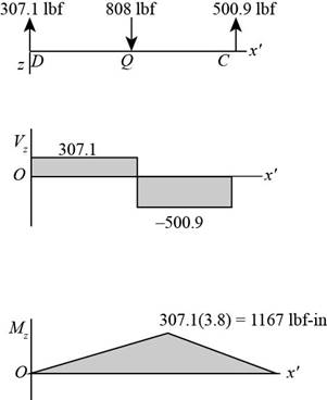
Figure (3)
Substitute
Substitute
Substitute
Substitute
Substitute
Substitute
Substitute
Write the expression for the maximum stress.
Substitute
Substitute
Refer to the Table A-20 “Deterministic ASTM Minimum Tensile and Yield Strengths for Some Hot-Rolled (HR) and Cold-Drawn (CD) Steels” to obtain the yield strength as
Substitute
Substitute
Refer to Table 6-2 “Parameters for Marin Surface Modification Factor” to obtain
Substitute
Substitute
Substitute
Substitute
Thus, the minimum factor of safety for fatigue based on infinite life is
Want to see more full solutions like this?
Chapter 6 Solutions
Shigley's Mechanical Engineering Design (McGraw-Hill Series in Mechanical Engineering)


- A tubular shaft being designed for use on a construction site must transmit 120 kW at 1,75 Hz, The inside diameter of the shaft is to be one-half of the outside diameter. If the allowable shear stress in the shaft is 45 MPa, what is the minimum required outside diameter d?arrow_forwardA crank arm consists of a solid segment of length bxand diameter rf, a segment of length bltand a segment of length byas shown in the figure. Two loads P act as shown: one parallel to — vand another parallel to —y. Each load P equals 1.2 kN. The crankshaft dimensions are A] = 75 mm, fr> = 125 mm, and b3= 35 mm. The diameter of the upper shaft isd = 22 mm, (a) Determine the maximum tensile, compressive, and shear stresses at point A, which is located on the surface of the shaft at the z axis. (b) Determine the maximum tensile, compressive, and shear stresses at point B, which is located on the surface of the shaft at the y axisarrow_forwardA magnesium-alloy wire of diameter d = 4mm and length L rotates inside a flexible tube in order to open or close a switch from a remote location (see figure). A torque Tis applied manually (either clockwise or counterclockwise) at end 5, thus twisting the wire inside the tube. At the other end A, the rotation of the wire operates a handle that opens or closes the switch. A torque T0 = 0.2 N · m is required to operate the switch. The torsional stiffness of the tube, combined with friction between the tube and the wire, induces a distributed torque of constant intensity t = 0.04N m/m (torque per unit distance) acting along the entire length of the wire. (a) If the allowable shear stress in the wire is T allow = 30 MPa, what is the longest permissible length Lmaxof the wire?arrow_forward
- The shaft in the figure is mounted with a gear wheel key. Shaft material 42CrMo4 The weight of the gear on the shaft is 0.9 kg, dimension, surface and notch factors KbK / Kç = 0.83, shaft speed n = 1120 rpm, shaft transmitted power 7.5 kW, force on shaft Fn = F = 2680 N Since the desired safety coefficient is Ssafe = 2; Check the safety of the shaftarrow_forwardA 1-in-diameter solid round bar has a groove 0.1-in deep with a 0.1-in radius machined into it. The bar is made of AISI 1020 CD steel and is subjected to a purely reversing torque of 1800 lb-in. For the S-N diagram of this material, let f=0.9. Estimate the number of cycles to failure. If the bar is also placed in an environment with a temperature of 750 F, estimate the number of cycles to failurearrow_forwardThe shaft shown in the figure is machined from AISI 1040 CD steel. The shaft rotates at 1600 rpm and is supported in rolling bearings at A and B. The applied forces are F1 = 1600 lbf and F2 = 640 lbf. A steady torque of 1600 lbf·in is being transmitted through the shaft between the points of application of the forces. ——————————————- Determine the endurance limit for this material as well as the value after correction for surface finish, sizing, and loading. (You must provide an answer before moving to the next part.) The endurance limit for this material is kpsi. The value after correction for surface finish, sizing, and loading is kpsi.arrow_forward
- The cold-drawn AISI 1040 Q&T at 205 ◦C steel bar shown in the figure is subjected to a completely reversed axial load fluctuating between 28 kN in compression to 28 kN in tension. Estimate the fatigue factor of safety based on achieving infinite life, and the yielding factor of safety for the following cases. If infinite life is not predicted, estimate the number of cycles to failure.a) for the part given in Fig 2(a) and b) for the part given in Fig. 2 (b) using the same dimensions (W=25mm, r=3mm, the thickness of 10 mm)arrow_forwardA rotating shaft of 25-mm diameter is simply supported by bearing reaction forces R1 and R2. The shaft is loaded with a transverse load of 13 kN as shown in the figure. The shaft is made from AISI 1045 hot-rolled steel. The surface has been machined. Determine a) The minimum static factor of safety based on yielding b) the endurance limit adjusted as necessary with Marin factors c) the minimum fatigue factor of safety based on achieving infinite life d) if the fatigue factor of safety is less than 1, then estimate the life of the part in number of rotationsarrow_forwardThe figure shows a shaft mounted in bearings at A and D and having pulleys at B and C. The forces shown acting on the pulley surfaces represent the belt tensions. The shaft is to be made of AISI 1035 CD steel. The shaft is rotating at speed of 1000 rpm. Find the minimum factor of safety for fatigue based on infinite life. If the life is not infinite, estimate the number of cycles. Be sure to check for yielding. Take shaft diameter to be 1.5 inches.arrow_forward
- A Steel shaft is subjected to an end thrust producing a stress of 90 MPa and the minimum shearing stress on the surface arising from torsion is 60 MPa .The yield point stress of the material in simple tension was found to be 300 MPa. calculate the factor of safety of the shaft according to the following theory 1)maximum shear stress theoryarrow_forwardA certain steel shafting material has an ultimate strength of 93 ksi, a notch radius of 0.25 inch, and a stress concentration factor of 2.5 at its pitch. Determine the fatigue-strength reduction factor for a life of 166,077 cycles onlyarrow_forwardAn input shaft of a gearbox with motor power P = 7 kW and rotation number n = 1300 rpm. The diameter of an input shaft is d = 20 mm and its material is 16MnCr5. A force of F = 2800 N forces the shaft due to the operation of a gear wheel connected with a wedge on the input shaft. The distances of the gear from the bearings are given as L₁ = 40 mm and L2 = 60 mm. In the most dangerous section, you are required to check the strength according to the S = 3 safety factor. If the section is unsafe in terms of strength, what changes would you make in the design to make it safe? (The surface of the spindle is machined as fine chips, reliability poor Kg = 1.).arrow_forward
 Mechanics of Materials (MindTap Course List)Mechanical EngineeringISBN:9781337093347Author:Barry J. Goodno, James M. GerePublisher:Cengage Learning