
Electric Circuits Fundamentals & Lab Mnl Pk
8th Edition
ISBN: 9780136125136
Author: Unknown
Publisher: PEARSON
expand_more
expand_more
format_list_bulleted
Concept explainers
Videos
Textbook Question
Chapter 6, Problem 58P
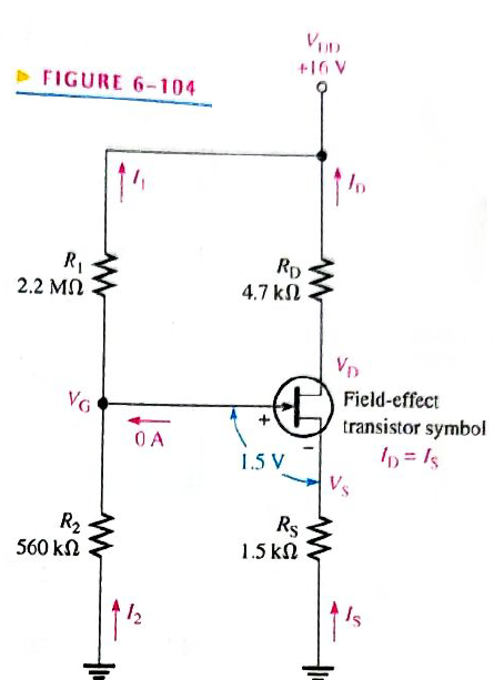
Figure 6-104 shows a dc biasing arrangement for a field-effect transistor amplifier. Biasing is a common method for setting up certain dc voltage levels required for proper amplifier operation. Although you may not be familiar with transistor amplifiers at this point, the dc voltages and currents in the circuit can be determined using methods that you already know.
- Find
- with respect to ground
- Determine
- Find
FIGURE 6-104
Expert Solution & Answer
Want to see the full answer?
Check out a sample textbook solution
Students have asked these similar questions
Instructions:
Use the nodal analysis technique to find the voltage at each of the nodes of the circuit in Figure 6.37, establishing the reference where you consider most convenient
(I want the procedure)
Answer:
The three values that should be of v, with any reference, but I checked these values in a simulator, and they should give
v = 5 v
v = 2.842 kv
v= 1.295 kv
A single-loop circuit contains two batteries, ε1 = 6 v , 0.25 Ω and ε2=16 v , 0.5 Ω, and are connected series-opposing.
An external resistance of 19.25 Ω is connected across their terminals.
Determine the terminal voltage of 6-v battery
1.
a) Design a combination circuit that has four LED’s and one resistor. Each LED will be in parallel and have its own switch. The circuit will have a resistor in series with the LED’s while they are connected in parallel. Each LED’s will drop 1.4vDC in parallel, with the same specifications. Make sure you size R1 (resistor R1) correctly using a VT of 9v. Each LED branch will have 20mA of current through it. Calculate all values including power at each component.
b) Also, if the 9v battery had a rating of 2 watt-hours, how long would it last? If you wanted to make each LED 1/3 brighter than the other in parallel, how would you change the circuit to make that happen? Explain and show calculations. (Hint… you do not need transistor(s), but you can use them in your design).
Chapter 6 Solutions
Electric Circuits Fundamentals & Lab Mnl Pk
Ch. 6 - Parallel resistors are always connected between...Ch. 6 - If one resistor is connected in series with a...Ch. 6 - In a series-parallel combinational circuit, the...Ch. 6 - A larger load resistor has a smaller loading...Ch. 6 - When measuring de voltage, a DMM will normally...Ch. 6 - When measuring de voltage, the input resistance of...Ch. 6 - When measuring & voltage, the input resistance of...Ch. 6 - A Thevenin circuit consists of a voltage source...Ch. 6 - The internal resistance of an ideal voltage source...Ch. 6 - To transfer maximum power to a load, the load...
Ch. 6 - Which of the following statements are true...Ch. 6 - The total resistance of Figure 6-73 can be found...Ch. 6 - If all of the resistors in Figure 6-73 have the...Ch. 6 - Prob. 4STCh. 6 - The parallel combination of a 330 resistor and a...Ch. 6 - In the circuit described in Question 5, the...Ch. 6 - Prob. 7STCh. 6 - The output of a certain voltage divider is 9V with...Ch. 6 - Prob. 9STCh. 6 - When a load resistance is connected to the output...Ch. 6 - The output voltage of a balanced Wheatstone bridge...Ch. 6 - Prob. 12STCh. 6 - In a certain two-source circuit, one source acting...Ch. 6 - Prob. 14STCh. 6 - Prob. 15STCh. 6 - You are measuring the voltage at a given point in...Ch. 6 - Prob. 1TSCCh. 6 - Determine the cause for each set of symtims. Refer...Ch. 6 - Prob. 3TSCCh. 6 - Determine the cause for each set of symptoms....Ch. 6 - Prob. 5TSCCh. 6 - Identify the series and parallel relationships in...Ch. 6 - Visualize and draw the following series-parallel...Ch. 6 - Visualize and draw the following series-parallel...Ch. 6 - In each circuit of Figure 6-76 identify the series...Ch. 6 - A certain circuit is composed of two parallel...Ch. 6 - For the circuit in Figure 6-77, determine the...Ch. 6 - Determine the total resistance for each circuit in...Ch. 6 - Determine the current through each resistor in...Ch. 6 - Determine the current through each resistor in...Ch. 6 - In Figure 6-78, find the following: total...Ch. 6 - In Figure 6-78, determine the current through R2...Ch. 6 - In Figure 6-78, determine the current through R4...Ch. 6 - A vlotage divider consists of two 56k resistors...Ch. 6 - A 12 V battery output is divided down to obtain...Ch. 6 - Which will cause a smaller decrease in output...Ch. 6 - In Figure 6-79, determine the current drain on the...Ch. 6 - Across which one of the following resistances will...Ch. 6 - A certain voltage divider consists of three 1.0M...Ch. 6 - What is the difference between the measured and...Ch. 6 - By what percentage does the voltmeter in Problem...Ch. 6 - A 10,000/VVOM is used on the 10 V scale to measure...Ch. 6 - If a DMM with 10M input resistance is used instead...Ch. 6 - A resistor of unknown value is connected to a...Ch. 6 - A bridge network is shown In Figure 6-80. To what...Ch. 6 - Determine the value of RX in the balance bridge in...Ch. 6 - Determine the outpur voltage of the unbalanced...Ch. 6 - Reduce the circuit in Figure 6-83 to its Thevenin...Ch. 6 - For each circuit in Figure 6-84, determine the...Ch. 6 - Determine the voltage and current for R1 in Figure...Ch. 6 - Determin the value of a load resistor connected...Ch. 6 - A certain Thevenin equivalent circuit has a...Ch. 6 - Determine the value of RL in Figure 6-84(a) for...Ch. 6 - In Figure 6-86, use ther superposition therorem to...Ch. 6 - In Figure 6-86, What is the curent through R2?...Ch. 6 - Is the voltmeter reading in Figure 6-87 correct?...Ch. 6 - If R2 in Figure 6-88 opens, what voltages will be...Ch. 6 - Check the meter readings in Figure 6-89 and locate...Ch. 6 - Determine the voltage you would expect to measure...Ch. 6 - Determine the voltage you would expect to measure...Ch. 6 - In each circuit of Figure 6-90, identify the...Ch. 6 - Draw the schematic of the PC board layout in...Ch. 6 - 1For the circuit shown in Figure 6-92, calculate...Ch. 6 - Determine the total resistance and the voltage at...Ch. 6 - Determine the total resistance between terminals A...Ch. 6 - What is the voltage across each resistor in Figure...Ch. 6 - Determine the voltage, VAB. in Figure 6-95. FIGURE...Ch. 6 - Find the value of R2 in Figure 6-96. FIGURE 6-96Ch. 6 - Determine the total resistance and the voltage at...Ch. 6 - Develop a voltage divider to provide a 6 V output...Ch. 6 - Determine the resistance values for a voltage...Ch. 6 - Using the superposition therorem, calculate the...Ch. 6 - Find the current through RL in Figure 6-99. FIGURE...Ch. 6 - Using Thevenin’s theorem, find the voltage...Ch. 6 - Determine VOUT for the circuit in Figure 6-101 for...Ch. 6 - Develop a schematic for the double-sided PC board...Ch. 6 - Lay out a PC board for the circuit in Figure...Ch. 6 - The voltage divider in Figure 6-103 has a switched...Ch. 6 - Figure 6-104 shows a dc biasing arrangement for a...Ch. 6 - Look at the voltmeters in Figure 6-105 and...Ch. 6 - Are the voltmeter reading in Figure 6-106 correct?...Ch. 6 - There is one fault in Figure 6-107. Bases on the...Ch. 6 - Look at the voltmeters in Figure 6-108 and...Ch. 6 - Determine the voltmeter reading in Figure 6-108 if...Ch. 6 - Open file P06-64; files are found at...Ch. 6 - www.prenhall.com/floyd. 65. Open file P06-65 and...Ch. 6 - www.prenhall.com/floyd. 66. Open file P06-66 and...Ch. 6 - www.prenhall.com/floyd. 67. Open file P06-67 and...Ch. 6 - www.prenhall.com/floyd. 68. Open file P06-68 and...Ch. 6 - www.prenhall.com/floyd. 69. Open file P06-69 and...Ch. 6 - www.prenhall.com/floyd. 70. Open file P06-70 and...Ch. 6 - www.prenhall.com/floyd. 71. Open file P06-71 and...
Knowledge Booster


Learn more about
Need a deep-dive on the concept behind this application? Look no further. Learn more about this topic, electrical-engineering and related others by exploring similar questions and additional content below.Similar questions
- I have been working on this problem for a while but I keep getting 5.6 W which is not the correct answer when I simplify it down it should just be the current source in parallel with the resistor and the voltage source so to me it makes sense that it should just be the current source multiplied by the voltage source which is 5.6 W the only discrepency I can think of is that when simplified the current going though the voltage source is the same direction as the curent source.arrow_forwardcan someone show me how to do this problem step by step please a device can be modeled as a current source in parallell wih a resistancearrow_forwardHow do I do the circuit shown in the schematic in a breadboardarrow_forward
- The image contains the problems that need to be solved. This is a voltage divider circuit, and it is understood that V0 is maximized when one of the resistors is at its maximum value while the other is at its minimum (and vice versa for the minimum V0). The answers are provided, but the process is needed.arrow_forwardSuggest 3 Capstone Design Project Ideas that is limited to Electrical Engineering.If there's an involvement of other Engineering Field, it still must be more on Electrical, like 70 per cent to 90 per cent of it must be electricalarrow_forwardDetermine the value of a load resistor connected between terminals A and B in Figure 6-82 for maximum power transfer to the load resistor.arrow_forward
- Determine the resistances R4 and R5 in Figure 6arrow_forwardGiven the circuit provided in Figure 4-30 (p. 194) and the fabrication parameters provided, find ID and VDS. VBias = 3.8V, VDD = 5V, RD= 1kΩ, RS = 1kΩ, Vt = 0.3V, kn = 100uA/V2. (NOTE: use Wolfram Alpha Equation Solver.) (b) Design a voltage divider circuit to create the bias voltage using resistors R1 and R2. Let the current through the voltage divider be in the range of 1mA to 10mA.arrow_forwardI am unsure about how to proceed in this problem, or if I even set it up correctly. Am I supposed to apply KCL to each Node, or set up a Supernode? I have 4 variables, but only came up with 3 equations.arrow_forward
arrow_back_ios
SEE MORE QUESTIONS
arrow_forward_ios
Recommended textbooks for you
 Introductory Circuit Analysis (13th Edition)Electrical EngineeringISBN:9780133923605Author:Robert L. BoylestadPublisher:PEARSON
 Delmar's Standard Textbook Of ElectricityElectrical EngineeringISBN:9781337900348Author:Stephen L. HermanPublisher:Cengage Learning
 Programmable Logic ControllersElectrical EngineeringISBN:9780073373843Author:Frank D. PetruzellaPublisher:McGraw-Hill Education
 Fundamentals of Electric CircuitsElectrical EngineeringISBN:9780078028229Author:Charles K Alexander, Matthew SadikuPublisher:McGraw-Hill Education
 Electric Circuits. (11th Edition)Electrical EngineeringISBN:9780134746968Author:James W. Nilsson, Susan RiedelPublisher:PEARSON
 Engineering ElectromagneticsElectrical EngineeringISBN:9780078028151Author:Hayt, William H. (william Hart), Jr, BUCK, John A.Publisher:Mcgraw-hill Education,
Introductory Circuit Analysis (13th Edition)
Electrical Engineering
ISBN:9780133923605
Author:Robert L. Boylestad
Publisher:PEARSON
Delmar's Standard Textbook Of Electricity
Electrical Engineering
ISBN:9781337900348
Author:Stephen L. Herman
Publisher:Cengage Learning
Programmable Logic Controllers
Electrical Engineering
ISBN:9780073373843
Author:Frank D. Petruzella
Publisher:McGraw-Hill Education
Fundamentals of Electric Circuits
Electrical Engineering
ISBN:9780078028229
Author:Charles K Alexander, Matthew Sadiku
Publisher:McGraw-Hill Education
Electric Circuits. (11th Edition)
Electrical Engineering
ISBN:9780134746968
Author:James W. Nilsson, Susan Riedel
Publisher:PEARSON
Engineering Electromagnetics
Electrical Engineering
ISBN:9780078028151
Author:Hayt, William H. (william Hart), Jr, BUCK, John A.
Publisher:Mcgraw-hill Education,
Current Divider Rule; Author: Neso Academy;https://www.youtube.com/watch?v=hRU1mKWUehY;License: Standard YouTube License, CC-BY