
Concept explainers
Videos
Using appropriate measurements and data, explain how to determine the bending stress in the blade.
C6–1
Answer to Problem 6.1CP
The bending stress in the blade is
Explanation of Solution
Given information:
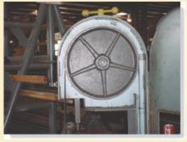
- The steel saw blade passes over the drive wheel of the band saw.
- Use appropriate measurements and data.
Explanation:
The contact area of the cable is upper half portion of the drive wheel. The, the upper half portion of the wheel will undergo stress.
Show the free-body diagram of the drive wheel as in Figure 1.
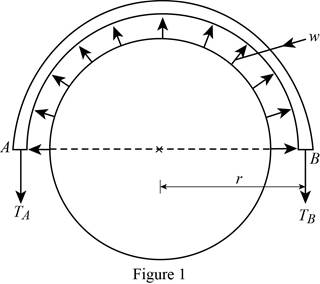
The force induced in the drive wheel will be uniformly distributed.
The circumferential distance of the circular section is
Convert the semi-circular section into beam section as in Figure 2.
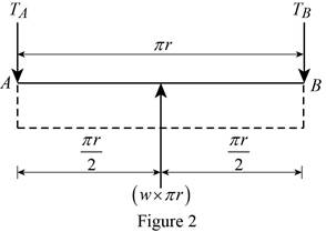
Determine the tension in the cable:
Moment about point A:
Determine the tension in the cable at point B by taking moment about point A.
Along the vertical direction:
Determine the tension in the cable at point A by resolving the vertical component of forces.
Show the calculation of values as follows:
Solve Equation (1).
Substitute
Maximum Bending moment:
The maximum bending moment will occur where the shear force changes sign
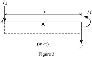
Consider a section at a distance x from left end of the beam.
Show the free body diagram of the section as in Figure 3.
Along the vertical direction:
Determine the shear force at the section by resolving the vertical component of forces.
Moment about the section:
Determine the moment at the section by taking moment about the section.
Substitute 0 for V and
Thus, the maximum bending moment will occur at a distance
Substitute
Bending stress:
Calculate the bending stress in the blade using the flexure formula.
Here, c is the distance between the centroid and the extreme fibre and I is moment of inertia of the band saw.
Consider the band saw is in rectangular cross section.
The value of c is
The moment of inertia of the band saw is
Here, b is width of the section and d is depth of the section.
Substitute
Thus, the bending stress in the blade is
Want to see more full solutions like this?
Chapter 6 Solutions
Modified Mastering Engineering with Pearson eText -- Standalone Access Card -- for Mechanics of Materials


- show the calculations for the Shear Body Diagram and Bending Moment Diagram.arrow_forwardWhat is the maximum normal stress, MPa, due to bending on section a-a? For W310x52, S = 748µm^3. Answer in whole numbers, no units. (Example: 123MPa --> 123)arrow_forwardDetermine the outer and inner diameter (in mm) of a hollow shaft that is required to carry a bending moment of 2000 N-m and a torque of 4300 N-m if the diameter of the hole is equal to 0.7 of the outer diameter of the shaft. The shaft rotates and loads are applied suddenly, with minor shocks. The maximum bending stress is equivalent to 88 N/mm2. Apply ASME Code for this problem.arrow_forward
- In determining the bending stress, what conclusion can be drawn if the neutral axis is an axis of symmetric of the cross-section? a. The maximum tensile and compression bending stresses are equal in magnitude and occur at the section of the largest bending moment. b. The maximum tensile and compression bending stresses are equal in magnitude and occur at the section of the smallest bending moment. c. None of the choices d. The maximum tensile and compressive bending stresses may occur in different sections.arrow_forwardCalculate the maximum normal bending stress and the maximum shear stressarrow_forwardI check it and it’s not correct for 1195.78 N Determine the maximum value of the bending moment and enter your answer in N-m units.. Remember to also show all your work Hint: Determine the shear and bending moment equations along the beam. Assume only concentrated loads at the front and rear axles.arrow_forward
- The beam safely supports shear forces and bending moments of 2kN and 6.5 kN-m respectively. Based on this criterion, can it be safely subjected to the loads F = 1kN and C = 1.6 kN-m? Use the area methodarrow_forwardDetermine the maximum absolute values of the shear and bending moment.arrow_forwardThe beam safely supports shear forces and bending moments of 2kN and 6.5 kN-m respectively. Based on this criterion, can it be safely subjected to the loads F = 1kN and C = 1.6 kN-m?arrow_forward
- An A-36 steel strap having a thickness of 10 mm and a width of 20 mm is bent into a circular arc of radius r = 10 m. Determine the maximum bending stress in the strap.arrow_forwardA11 Consider the cutaway diagram provided above. Using this, identify and describe a structural component or sub-structure that carries bending. You should sketch and describe an idealisation of the structural component suitable for analysing the bending response, and describe how the structural component may fail under bending.arrow_forwardThe change in moment is equal to _________ a.Rotational moment b. total weight c. bending moment d. Area under the shear diagramarrow_forward
 Elements Of ElectromagneticsMechanical EngineeringISBN:9780190698614Author:Sadiku, Matthew N. O.Publisher:Oxford University Press
 Mechanics of Materials (10th Edition)Mechanical EngineeringISBN:9780134319650Author:Russell C. HibbelerPublisher:PEARSON
 Thermodynamics: An Engineering ApproachMechanical EngineeringISBN:9781259822674Author:Yunus A. Cengel Dr., Michael A. BolesPublisher:McGraw-Hill Education
 Control Systems EngineeringMechanical EngineeringISBN:9781118170519Author:Norman S. NisePublisher:WILEY
 Mechanics of Materials (MindTap Course List)Mechanical EngineeringISBN:9781337093347Author:Barry J. Goodno, James M. GerePublisher:Cengage Learning
 Engineering Mechanics: StaticsMechanical EngineeringISBN:9781118807330Author:James L. Meriam, L. G. Kraige, J. N. BoltonPublisher:WILEY