Concept explainers
Videos
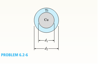
A r o lukI f/frm f «m t ub e of ou t sid e d ia met er ^ and a copper core of diameter dxare bonded to form a composite beam, as shown in the figure,
(a) Derive formulas for the allowable bending moment M that can be carried by the beam based upon an allowable stress <7Ti in the titanium and an allowable stress
copper (Assume that the moduli of elasticity for the titanium and copper are Er- and £Cu, respectively.)
(b)
If d1= 40 mm, d{= 36 mm, ETl= 120 GPa, ECu= 110 GPa, o-Ti = 840 MPa, and
ctqj = 700 MPa, what is the maximum bending moment Ml (c)
What new value of copper diameter dtwill result
in a balanced design? (i.e., a balanced design is
that in which titanium and copper reach allow-
able stress values at the same time).
i.
The formula for the allowable bending moment M for titanium tube and copper core of the composite beam
Answer to Problem 6.2.6P
Explanation of Solution
Given:
Allowable stress for titanium is sti
Allowable stress for titanium is scu
Diameter of the copper rod = d1
Outer Diameter of the titanium rod = d2
Concept Used:
Calculation:
Conclusion:
ii.
The allowable bending moment for titanium and copper.
Answer to Problem 6.2.6P
Allowable bending moment for titanium, Mallowableti = 4989 N-m
Allowable bending moment for Copper, MallowableCu =5039.6 N-m
Explanation of Solution
Given:
Allowable stress for titanium, sti = 840 MPa
Allowable stress for titanium, scu= 700 MPa
Diameter of the copper rod, d1= 36 mm
Outer Diameter of the titanium rod, d2 = 40 mm
Eti= 110 GPa
Ecu= 120 GPa
Concept Used:
Calculation:
Allowable bending moment for titanium, Mallowableti = 4989 N-m
Allowable bending moment for Copper, MallowableCu =5039.6 N-m
iii.
The value of the diameter of the copper rod for a balanced design
Answer to Problem 6.2.6P
The diameter of the copper for a balanced design is 36.4 mm
Explanation of Solution
Given:
Allowable stress for titanium, sti = 840 MPa
Allowable stress for titanium, scu= 700 MPa
Outer Diameter of the titanium rod, d2 = 40 mm
Eti= 110 GPa
Ecu= 120 GPa
Concept Used:
Calculation:
Conclusion:
The diameter of the copper for a balanced design is 36.4 mm
Want to see more full solutions like this?
Chapter 6 Solutions
Mechanics of Materials - Text Only (Looseleaf)


- A steel beam of rectangular cross section is 40 mm wide and 80 mm high (see figure). The yield stress of the steel is 210 MPa, (a) What percent of the cross-sectional area is occupied by the clastic core if the beam is subjected to a bending moment of 12.0 kN · m acting about the z axis? (b) What is the magnitude of the bending moment that will cause 50% of the cross section to yield?arrow_forwardA wood beam with cross-sectional dimensions 200 mm x 300 mm is reinforced on its sides by steel plates 12 mm thick (see figure). The moduli of elasticity for the steel and wood are E±= 190 GPa and Ew= 11 GPa, respectively. Also, the corresponding allowable stresses are eS= 110 MPa and ew = 7.5 MPa, (a) Calculate the maximum permissible bending moment Mmaxwhen the beam is bent about the- axis. Repeat part (a) if the beam is now bent about its y axis. Find the required thickness of the steel plates on the beam bent about the y axis so that Mmaxis the same for both beam orientations.arrow_forwardA reinforced concrete T-beam (see figure) is acted on by a positive bending moment of M = 175 kip-ft. Steel reinforcement consists of four bars of 1.41-inch diameter. The modulus of elasticity for the concrete is Ec= 3000 ksi while that of the steel is £s = 29,000 ksi. Let b = 48 im, rf = 4 in., bw=15 in,, and d = 24 in, Find the maximum stresses in steel and concrete, If allowable stresses for concrete and steel are o"ac = 1400 psi and tr^ =18 ksi, respectively, what is the maximum permissible positive bending moment?arrow_forward
- The hollow box beam shown in the figure is subjected to a bending moment M of such magnitude that the flanges yield but the webs remain linearly elastic. (a) Calculate the magnitude of the moment M if the dimensions of the cross section are A = 15 in., A] = 12.75 in., h = 9 in., and ey =7.5 in. Also, the yield stress is eY = 33 ksi. (b) What percent of the moment M is produced by the elastic core?arrow_forwardA hollow box beam with height h = 16 in,, width h = 8 in,, and constant wall thickness r = 0.75 LiL is shown in the figure. The beam is constructed of steel with yield stress ty = 32 ksi. Determine the yield moment My, plastic moment A/p, and shape factor.arrow_forwardA simple beam that is 18 ft long supports a uniform load of intensity q. The beam is constructed of two C8 x 11.5 sections (channel sections or C-shapes) on either side of a 4 × 8 (actual dimensions) wood beam (see the cross section shown in the figure part a). The modulus of elasticity of the steel (E; = 30,000 ksi) is 20 times that of the wood (Ew). (a) If the allowable stresses in the steel and wood are 12,000 psi and 900 psi, respectively, what is the allowable load qmax Note: Disregard the weight of the beam, and see Table F-3(a) of Appendix F for the dimensions and properties of the C-shape beam. (b) If the beam is rotated 90° to bend about its v axis (see figure part b) and uniform load q = 250 lb/ft is applied, find the maximum stresses trs and crw in the steel and wood, respectively Include the weight of the beam. (Assume weight densities of 35 lb/ft3 and 490 lb/ft3 for the wood and steel, respectively.)arrow_forward
- The cross section of a sand wie h beam consisting of aluminum alloy faces and a foam core is shown in the figure. The width b of the beam is 8.0 in, the thickness I of the faces is 0.25 in., and the height hcof the core is 5.5 in. (total height h = 6.0 in). The moduli of elasticity are 10.5 × 10⁶ psi for the aluminum faces and 12.000 psi for the foam core. A bending moment M = 40 kip-in. acts about the z axis. Determine the maximum stresses in the faces and the core using (a) the general theory for composite beams and (b) the approximate theory for sandwich beams.arrow_forwardA sandwich beam having steel faces enclosing a plastic core is subjected to a bending moment M = 5 kN · m. The thickness of each steel face is 1 = 3 mm with modulus of elasticity E = 200 GPa, The height of the plastic core is hp= 140 mm, and its modulus of elasticity is Ep= 800 MPa. The overall dimensions of the beam are h = 146 mm and h = 175 mm. Using the transformed-section method, determine the maximum tensile and compressive stresses in the faces and the core.arrow_forwardA reinforced concrete beam (see figure) is acted on by a positive bending moment of M = 160 kN · m. Steel reinforcement consists of 4 bars of 28 mm diameter. The modulus of elasticity for the concrete is Ec= 25 GPa while that of the steel is Es= 200 GPa. Find the maximum stresses in steel and concrete. If allowable stresses for concrete and steel are T2= 9.2 MPa and t1= 135 MPa, respectively, what is the maximum permissible positive bending moment? What is the required area of steel reinforcement, A$ if a balanced condition must be achieved? What is the allowable positive bending moment? (Recall that in a balanced design, both steel and concrete reach allowable stress values simultaneously under the design moment.)arrow_forward
- A cantilever beam has a length L = 12 ft and a rectangular cross section (b = 16 in., h = 24 in.), A linearly varying distributed load with peak intensity q0acts on the beam, (a) Find peak intensity q0if the deflection at joint B is known to be 0.18 in. Assume that modulus E = 30,000 ksi. (b) Find the location and magnitude of the maximum rotation of the beam.arrow_forwardA cantilever beam AB of length L = 6.5 ft supports a trapezoidal distributed load of peak intensity 4, and minimum intensity q/2tthat includes the weight of the beam (see figure). The beam is a steel W 12 × 14 wide-flange shape (see Table F-l(a), Appendix F). Calculate the maximum permissible load q based upon (a) an allowable bending stress eallow = 18 ksi and (b) an allowable shear stress eallow = 7,5 ksi. Note: Obtain the moment of inertia and section modulus of the beam from Table F-l(a).arrow_forwardA C 200 x 17.1 channel section has an angle with equal legs attached as shown; the angle serves as a lintel beam. The combined steel section is subjected to a bending moment M having its vector directed along the z axis, as shown in the figure. The cent roi d C of the combined section is located at distances xtand ycfrom the centroid (C1) of the channel alone. Principal axes yl and yvare also shown in the figure and properties Ix1,Iy1and 0pare given. Find the orientation of the neutral axis and calculate the maximum tensile stress exand maximum compressive stress if the angle is an L 76 x 76 x 6.4 section and M = 3.5 kN - m. Use the following properties for principal axes for the combined section:/^, = 18.49 X 10⁶ nrai4,/;| = 1.602 X 106 mm4, ep= 7.448*(CW),_r£ = 10.70 mm,andvf= 24.07 mm.arrow_forward
 Mechanics of Materials (MindTap Course List)Mechanical EngineeringISBN:9781337093347Author:Barry J. Goodno, James M. GerePublisher:Cengage Learning