
Videos
(a)
The temperature rise in open die forging of cylinder for no friction between the flat dies and the specimen.
(a)
Explanation of Solution
Given:
The initial thickness of the specimen is
The initial radius of the specimen is
The friction coefficient is
Formula used:
The expression for the flow stress is given as,
Here,
The expression for the true strain is given as,
Here,
The expression for the final radius by equating the volume is given as,
The expression for the forging force is given as,
Here,
The expression for the average pressure is given as,
The expression for final height for
The expression for final height for
The expression forfinal height for
The expression for final height for
The expression for final height for
The expression for the temperature rise is given as,
Here
Calculation:
For
The final height can be calculated as,
The final radius can be calculated as,
The true strain can be calculated as,
The flow stress can be calculated as,
Refer to table 2.2 “Typical values of strength coefficient
The average pressure can be calculated as,
The forging force can be calculated as,
For
The final height can be calculated as,
The final radius can be calculated as,
The true strain can be calculated as,
The flow stress can be calculated as,
Refer to table 2.2 “Typical values of strength coefficient
The average pressure can be calculated as,
The forging force can be calculated as,
For
The final height can be calculated as,
The final radius can be calculated as,
The true strain can be calculated as,
The flow stress can be calculated as,
Refer to table 2.2 “Typical values of strength coefficient
The average pressure can be calculated as,
The forging force can be calculated as,
For
The final height can be calculated as,
The final radius can be calculated as,
The true strain can be calculated as,
The flow stress can be calculated as,
Refer to table 2.2 “Typical values of strength coefficient
The average pressure can be calculated as,
The forging force can be calculated as,
For
The final height can be calculated as,
The final radius can be calculated as,
The true strain can be calculated as,
The flow stress can be calculated as,
Refer to table 2.2 “Typical values of strength coefficient
The average pressure can be calculated as,
The forging force can be calculated as,
For
| Reduction (in ) | Forging force (in ) | Area under curve (in ) |
| 2.1635 |
Work done can be calculated by the summation of the area under the curve.
Refer to table of properties of common engineering materials “Typical values of density and heat capacity” for annealed copper is,
Change in temperature can be calculated as,
The figure (1) shows the curve between the forging force and reduction in height.
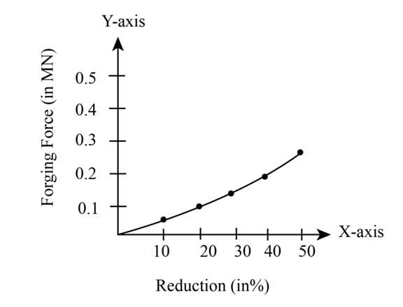
Figure (1)
(b)
The temperature risein open die forging of cylinder for
(b)
Explanation of Solution
Given:
The initial thickness of the specimen is
The initial radius of the specimen is
The friction coefficient is
Formula used:
The expression for the flow stress is given as,
Here,
The expression for the true strain is given as,
Here,
The expression for the final radius by equating the volume is given as,
The expression for the forging force is given as,
Here,
The expression for the average pressure is given as,
The expression for final height for
The expression for final height for
The expression forfinal height for
The expression for final height for
The expression for final height for
The expression for the temperature rise is given as,
Here
Calculation:
For
The final height can be calculated as,
The final radius can be calculated as,
The true strain can be calculated as,
The flow stress can be calculated as,
Refer to table 2.2 “Typical values of strength coefficient
The average pressure can be calculated as,
The forging force can be calculated as,
For
The final height can be calculated as,
The final radius can be calculated as,
The true strain can be calculated as,
The flow stress can be calculated as,
Refer to table 2.2 “Typical values of strength coefficient
The average pressure can be calculated as,
The forging force can be calculated as,
For
The final height can be calculated as,
The final radius can be calculated as,
The true strain can be calculated as,
The flow stress can be calculated as,
Refer to table 2.2 “Typical values of strength coefficient
The average pressure can be calculated as,
The forging force can be calculated as,
For
The final height can be calculated as,
The final radius can be calculated as,
The true strain can be calculated as,
The flow stress can be calculated as,
Refer to table 2.2 “Typical values of strength coefficient
The average pressure can be calculated as,
The forging force can be calculated as,
For
The final height can be calculated as,
The final radius can be calculated as,
The true strain can be calculated as,
The flow stress can be calculated as,
Refer to table 2.2 “Typical values of strength coefficient
The average pressure can be calculated as,
The forging force can be calculated as,
For
| Reduction (in ) | Forging force (in ) | Area under curve (in ) |
Work done can be calculated by the summation of the area under the curve.
Refer to table of properties of common engineering materials “Typical values of density and heat capacity” for annealed copper is,
Change in temperature can be calculated as,
The figure (2) shows the curve between the forging force and reduction in height.
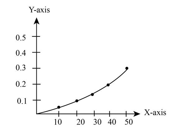
Figure (2)
Want to see more full solutions like this?
Chapter 6 Solutions
EBK MANUFACTURING PROCESSES FOR ENGINEE


- A prismatic bar at 10 degrees celsius in a rigid conrete wall at both ends. The bar is 1000 mm long and has a cross-sectional area of 2600mm^2. What is most nearly the axial force in the bar if the temperature is raised at 40 to degrees celsius?arrow_forwardA superalloy gas turbine component was originally designed to operate at temperatures up to 760°C and exhibited a stress rupture life of 900 h under this operating condition. An updated design calls for a thermal barrier coating to be added to the same component to allow engine operation under the same conditions, but with an increase in reliability. If an increase in rupture life to 1800 h is desired, what temperature differential between the inside and outside of the component must be achieved by the addition of the TBC?arrow_forwardThe strength coefficient and strain-hardening exponent of a certain test metal are 750 MPa and 0.25, respectively. A cylindrical specimen of the metal with starting diameter = 75 mm is stretched. If the average flow stress on the part is 450 MPa determine the final diameter of the specimen.arrow_forward
- For safe and reliable operation, a certain polypropylene pipe must withstand an internal pressure of 0.5 MPa for a minimum of three years. If the pipe diameter is 100 mm, what is the minimum necessary wall thickness to ensure that the pipe will not experience a strain greater than 1.3%? To solve this problem, use the accompanying graph that reveals the room temperature creep response for polypropylene.arrow_forwardCold forming method is applied to many metals and alloys such as steel, aluminum, copper at room temperature and temperatures below it, its strength increases after cold. Explain the factor that causes increased material strength.arrow_forwardDerive the temperature trend in a multilayer material made of 2 slabs alluminum (λ1 and λ2) with air between them (h).arrow_forward
- Mica sheet of 0.15 m diameter and has thickness of 0.005m is subjected to heater with a supply of 28W power. Cold water is circulated around the specimen with a temperature of 30°C; calculate the thermal conductivity of the specimen?arrow_forwardThe compressive strength of alumina quartz (Al2O3) is 2.1 GPa. A quartz tube is being used for a vacuum furnace. Both ends of the tube are constrained and cannot move. To what temperature can the tube be heated up from room temperature such that the tube won’t fracture due to the thermal stress?arrow_forwardThe strength coefficient and strain-hardening exponent of a certain test metal are 500MPa and 0.25 respectively. A cylindrical specimen of the metal with starting diameter = 58 mm is stretched. If the average flow stress on the part is 375 MPa determine the final diameter of the specimen.arrow_forward
- A mechanic needs to remove a tight fitting pin of material A from a hole in a block made of material B. The machinist heats both the pin and the block to the same high temperature and removes the pin easily. What statement relates the coefficient of thermal expansion of material A to that of material B?arrow_forwardTo manufacture a piston with a circular cross section, an alloy steel bar is required whose length is fixed and has a value of 35 cm and must withstand a compression load of 5.2 tons. For its design, a safety factor of 4/5 is suggested with respect to the yield stress. The shear modulus for that alloy is 80 GPa.To know the resistance of this steel alloy, a compression test was carried out on a specimen of the same material, from this test the data table of stress against engineering deformation shown was obtained. Image 1 1) Calculate the increase in the diameter of the bar when the load is applied2) Define the Poisson's ratio and calculate its valuearrow_forwardDefine the thermal conductivities of some materials at room conditionsarrow_forward
 Principles of Heat Transfer (Activate Learning wi...Mechanical EngineeringISBN:9781305387102Author:Kreith, Frank; Manglik, Raj M.Publisher:Cengage Learning