EBK MANUFACTURING PROCESSES FOR ENGINEE
6th Edition
ISBN: 8220106714393
Author: Schmid
Publisher: YUZU
bartleby

Concept explainers

bartleby

Videos

Question
Book Icon
Chapter 6, Problem 6.77P

(a)

To determine

The work-done in open die forging of cylinder for no friction between the flat dies and the specimen.

(a)

Expert Solution
Check Mark

Explanation of Solution

Given:

The initial thickness of the specimen is ho=10mm .

The initial radius of the specimen is do=25mm .

The friction coefficient is μ=0 .

Formula used:

The expression for the flow stress is given as,

  σf=Kεn …… (1)

Here, σf is the flow stress, K is the strength coefficient, ε is the true strain, n is the strain hardening coefficient.

The expression for the true strain is given as,

  ε=ln(hohf)

Here, hf is the final thickness.

The expression for the final radius by equating the volume is given as,

  df2=do2hohf

The expression for the forging force is given as,

  F=paπdf24

Here, pa is the average pressure.

The expression for the average pressure is given as,

  pa=σf(1+μdf3hf)

The expression for final height for 10% reduction in height in given as,

  ( h o h f h o )×100%=10%hf=0.9ho

The expression for final height for 20% reduction in height in given as,

  ( h o h f h o )×100%=20%hf=0.8ho

The expression forfinal height for 30% reduction in height in given as,

  ( h o h f h o )×100%=30%hf=0.7ho

The expression for final height for 40% reduction in height in given as,

  ( h o h f h o )×100%=40%hf=0.6ho

The expression for final height for 50% reduction in height in given as,

  ( h o h f h o )×100%=50%hf=0.5ho

Calculation:

For 10% reduction,

The final height can be calculated as,

  hf=0.9hohf=0.9×10mmhf=9mm

The final radius can be calculated as,

  df2=do2hohfdf2= ( 25mm )2×10mm9mmdf=26.35mm

The true strain can be calculated as,

  ε=ln( h o h f )ε=ln( 10mm 9mm)ε=0.1053

The flow stress can be calculated as,

  σf=Kεnσf=315MPa×(0.10536)0.54σf=93.44MPa

Refer to table 2.2 “Typical values of strength coefficient K and strength hardening exponent n ” for annealed copper is,

  K=580MPan=0.34

The average pressure can be calculated as,

  pa=σf(1+ μ d f 3 h f )pa=93.44MPa×(1+ 0×26.35mm 3×9mm)pa=93.44MPa

The forging force can be calculated as,

  F=paπdf24F=93.44MPa×3.14×( 26.35mm)42F=50928N( 1MN 10 6 N)F=0.050928MN

For 20% reduction,

The final height can be calculated as,

  hf=0.8hohf=0.8×10mmhf=8mm

The final radius can be calculated as,

  df2=do2hohfdf2= ( 25mm )2×10mm8mmdf=27.95mm

The true strain can be calculated as,

  ε=ln( h o h f )ε=ln( 10mm 8mm)ε=0.223

The flow stress can be calculated as,

  σf=Kεnσf=315MPa×(0.223)0.54σf=140.135MPa

Refer to table 2.2 “Typical values of strength coefficient K and strength hardening exponent n ” for annealed copper is,

  K=580MPan=0.34

The average pressure can be calculated as,

  pa=σf(1+ μ d f 3 h f )pa=140.135MPa×(1+ 0×27.95mm 3×8mm)pa=140.135MPa

The forging force can be calculated as,

  F=paπdf24F=140.135MPa×3.14×( 27.95mm)42F=85936N( 1MN 10 6 N)F=0.085MN

For 30% reduction,

The final height can be calculated as,

  hf=0.7hohf=0.7×10mmhf=7mm

The final radius can be calculated as,

  df2=do2hohfdf2= ( 25mm )2×10mm7mmdf=29.88mm

The true strain can be calculated as,

  ε=ln( h o h f )ε=ln( 10mm 7mm)ε=0.3566

The flow stress can be calculated as,

  σf=Kεnσf=315MPa×(0.3566)0.54σf=180.525MPa

Refer to table 2.2 “Typical values of strength coefficient K and strength hardening exponent n ” for annealed copper is,

  K=580MPan=0.34

The average pressure can be calculated as,

  pa=σf(1+ μ d f 3 h f )pa=180.525MPa×(1+ 0×29.88mm 3×7mm)pa=180.525MPa

The forging force can be calculated as,

  F=paπdf24F=180.525MPa×3.14×( 29.88mm)42F=126522N( 1MN 10 6 N)F=0.1265MN

For 40% reduction,

The final height can be calculated as,

  hf=0.6hohf=0.6×10mmhf=6mm

The final radius can be calculated as,

  df2=do2hohfdf2= ( 25mm )2×10mm6mmdf=32.275mm

The true strain can be calculated as,

  ε=ln( h o h f )ε=ln( 10mm 6mm)ε=0.5108

The flow stress can be calculated as,

  σf=Kεnσf=315MPa×(0.5108)0.54σf=219.17MPa

Refer to table 2.2 “Typical values of strength coefficient K and strength hardening exponent n ” for annealed copper is,

  K=580MPan=0.34

The average pressure can be calculated as,

  pa=σf(1+ μ d f 3 h f )pa=219.17MPa×(1+ 0×32.275mm 3×6mm)pa=219.17MPa

The forging force can be calculated as,

  F=paπdf24F=219.17MPa×3.14×( 32.275mm)42F=179218N( 1MN 10 6 N)F=0.1792MN

For 50% reduction,

The final height can be calculated as,

  hf=0.5hohf=0.5×10mmhf=5mm

The final radius can be calculated as,

  df2=do2hohfdf2= ( 25mm )2×10mm5mmdf=35.35mm

The true strain can be calculated as,

  ε=ln( h o h f )ε=ln( 10mm 5mm)ε=0.69

The flow stress can be calculated as,

  σf=Kεnσf=315MPa×(0.69)0.54σf=258.437MPa

Refer to table 2.2 “Typical values of strength coefficient K and strength hardening exponent n ” for annealed copper is,

  K=580MPan=0.34

The average pressure can be calculated as,

  pa=σf(1+ μ d f 3 h f )pa=258.437MPa×(1+ 0×35.35mm 3×5mm)pa=258.437MPa

The forging force can be calculated as,

  F=paπdf24F=258.437MPa×3.14×( 35.35mm)42F=253514N( 1MN 10 6 N)F=0.2535MN

For μ=0 ,

    Reduction (in %
    )
    Forging force (in MN
    )
    Area under curve (in mmkg
    )
    100.05090.509
    200.0850.72
    300.12651.025
    400.17921.5285
    500.25352.1635

Work done can be calculated by calculating the sum of area under the curve.

  Workdone=5.964mmkg

The figure (1) shows the curve between the forging force and reduction in height,
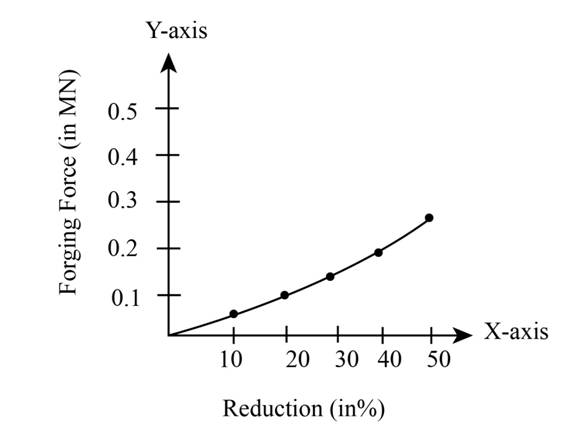
  EBK MANUFACTURING PROCESSES FOR ENGINEE, Chapter 6, Problem 6.77P , additional homework tip  1

Figure (1)

(b)

To determine

The work-done in open die forging of cylinder for μ=0.1 between the flat dies and the specimen.

(b)

Expert Solution
Check Mark

Explanation of Solution

Given:

The initial thickness of the specimen is ho=10mm .

The initial radius of the specimen is do=25mm .

The friction coefficient is μ=0.1 .

Formula used:

The expression for the flow stress is given as,

  σf=Kεn …… (1)

Here, σf is the flow stress, K is the strength coefficient, ε is the true strain, n is the strain hardening coefficient.

The expression for the true strain is given as,

  ε=ln(hohf)

Here, hf is the final thickness.

The expression for the final radius by equating the volume is given as,

  df2=do2hohf

The expression for the forging force is given as,

  F=paπdf24

Here, pa is the average pressure.

The expression for the average pressure is given as,

  pa=σf(1+μdf3hf)

The expression for final height for 10% reduction in height in given as,

  ( h o h f h o )×100%=10%hf=0.9ho

The expression for final height for 20% reduction in height in given as,

  ( h o h f h o )×100%=20%hf=0.8ho

The expression forfinal height for 30% reduction in height in given as,

  ( h o h f h o )×100%=30%hf=0.7ho

The expression for final height for 40% reduction in height in given as,

  ( h o h f h o )×100%=40%hf=0.6ho

The expression for final height for 50% reduction in height in given as,

  ( h o h f h o )×100%=50%hf=0.5ho

Calculation:

For 10% reduction,

The final height can be calculated as,

  hf=0.9hohf=0.9×10mmhf=9mm

The final radius can be calculated as,

  df2=do2hohfdf2= ( 25mm )2×10mm9mmdf=26.35mm

The true strain can be calculated as,

  ε=ln( h o h f )ε=ln( 10mm 9mm)ε=0.1053

The flow stress can be calculated as,

  σf=Kεnσf=315MPa×(0.10536)0.54σf=93.44MPa

Refer to table 2.2 “Typical values of strength coefficient K and strength hardening exponent n ” for annealed copper is,

  K=580MPan=0.34

The average pressure can be calculated as,

  pa=σf(1+ μ d f 3 h f )pa=93.44MPa×(1+ 0.1×26.35mm 3×9mm)pa=102.56MPa

The forging force can be calculated as,

  F=paπdf24F=102.56MPa×3.14×( 26.35mm)42F=58898N( 1MN 10 6 N)F=0.05889MN

For 20% reduction,

The final height can be calculated as,

  hf=0.8hohf=0.8×10mmhf=8mm

The final radius can be calculated as,

  df2=do2hohfdf2= ( 25mm )2×10mm8mmdf=27.95mm

The true strain can be calculated as,

  ε=ln( h o h f )ε=ln( 10mm 8mm)ε=0.223

The flow stress can be calculated as,

  σf=Kεnσf=315MPa×(0.223)0.54σf=140.135MPa

Refer to table 2.2 “Typical values of strength coefficient K and strength hardening exponent n ” for annealed copper is,

  K=580MPan=0.34

The average pressure can be calculated as,

  pa=σf(1+ μ d f 3 h f )pa=140.135MPa×(1+ 0.1×27.95mm 3×8mm)pa=156.454MPa

The forging force can be calculated as,

  F=paπdf24F=156.454MPa×3.14×( 27.95mm)42F=95943.4N( 1MN 10 6 N)F=0.0959MN

For 30% reduction,

The final height can be calculated as,

  hf=0.7hohf=0.7×10mmhf=7mm

The final radius can be calculated as,

  df2=do2hohfdf2= ( 25mm )2×10mm7mmdf=29.88mm

The true strain can be calculated as,

  ε=ln( h o h f )ε=ln( 10mm 7mm)ε=0.3566

The flow stress can be calculated as,

  σf=Kεnσf=315MPa×(0.3566)0.54σf=180.525MPa

Refer to table 2.2 “Typical values of strength coefficient K and strength hardening exponent n ” for annealed copper is,

  K=580MPan=0.34

The average pressure can be calculated as,

  pa=σf(1+ μ d f 3 h f )pa=180.525MPa×(1+ 0.1×29.88mm 3×7mm)pa=206.211MPa

The forging force can be calculated as,

  F=paπdf24F=206.211MPa×3.14×( 29.88mm)42F=144524N( 1MN 10 6 N)F=0.1445MN

For 40% reduction,

The final height can be calculated as,

  hf=0.6hohf=0.6×10mmhf=6mm

The final radius can be calculated as,

  df2=do2hohfdf2= ( 25mm )2×10mm6mmdf=32.275mm

The true strain can be calculated as,

  ε=ln( h o h f )ε=ln( 10mm 6mm)ε=0.5108

The flow stress can be calculated as,

  σf=Kεnσf=315MPa×(0.5108)0.54σf=219.17MPa

Refer to table 2.2 “Typical values of strength coefficient K and strength hardening exponent n ” for annealed copper is,

  K=580MPan=0.34

The average pressure can be calculated as,

  pa=σf(1+ μ d f 3 h f )pa=219.17MPa×(1+ 0.1×32.275mm 3×6mm)pa=258.47MPa

The forging force can be calculated as,

  F=paπdf24F=258.47MPa×3.14×( 32.275mm)42F=211354N( 1MN 10 6 N)F=0.2113MN

For 50% reduction,

The final height can be calculated as,

  hf=0.5hohf=0.5×10mmhf=5mm

The final radius can be calculated as,

  df2=do2hohfdf2= ( 25mm )2×10mm5mmdf=35.35mm

The true strain can be calculated as,

  ε=ln( h o h f )ε=ln( 10mm 5mm)ε=0.69

The flow stress can be calculated as,

  σf=Kεnσf=315MPa×(0.69)0.54σf=258.437MPa

Refer to table 2.2 “Typical values of strength coefficient K and strength hardening exponent n ” for annealed copper is,

  K=580MPan=0.34

The average pressure can be calculated as,

  pa=σf(1+ μ d f 3 h f )pa=258.437MPa×(1+ 0.1×35.35mm 3×5mm)pa=319.34MPa

The forging force can be calculated as,

  F=paπdf24F=319.34MPa×3.14×( 35.35mm)42F=313256N( 1MN 10 6 N)F=0.3132MN

For μ=0.1

    Reduction (in %
    )
    Forging force (in MN
    )
    Area under curve (in mmkg
    )
    100.058890.294
    200.09590.774
    300.14451.202
    400.21131.779
    500.31322.6225

Work done can be calculated by calculating the sum of area under the curve.

  Workdone=6.6715mmkg

The figure (2) shows the curve between the forging force and reduction in height,
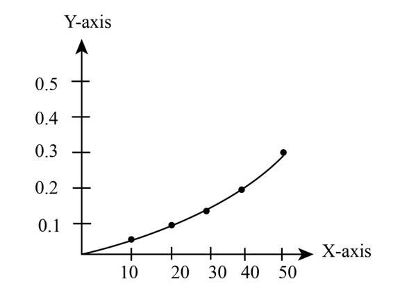
  EBK MANUFACTURING PROCESSES FOR ENGINEE, Chapter 6, Problem 6.77P , additional homework tip  2

Figure (2)

Want to see more full solutions like this?

Subscribe now to access step-by-step solutions to millions of textbook problems written by subject matter experts!
Students have asked these similar questions
A solid cylindrical work piece is reduced in height by an open die forging process using flat dies on a mechanical press, powered by a 20 kW motor which operates at 35 strokes per minute with a stroke length of 160 mm. The work piece is 60 mm high and 100 mm in diameter and is to be reduced in height by 15%. The coefficient of friction during the operation is 0,18. Calculate the flow stress of work piece material if the press is set to operate at 90% of its maximum capacity.
Explain what is the effective-slenderness ratio?
A cold rolling operation is to be used to reduce a 50 mm thick and 200 mm wide copper plate. The entering velocity of the plate is 15 m/min and the exit velocity is 18 m/min. The coefficient of friction is 0.2 and assuming that the reduction in thickness during this process is the maximum draft permissible. If the plate widens by 5% after rolling, calculate the power required to drive the rolls. Assume average flow stress of the material as 180 MPa.

Chapter 6 Solutions

EBK MANUFACTURING PROCESSES FOR ENGINEE

Ch. 6 - Prob. 6.11QCh. 6 - Prob. 6.12QCh. 6 - Prob. 6.13QCh. 6 - Prob. 6.14QCh. 6 - Prob. 6.15QCh. 6 - Prob. 6.16QCh. 6 - Prob. 6.17QCh. 6 - Prob. 6.18QCh. 6 - Prob. 6.19QCh. 6 - Prob. 6.20QCh. 6 - Prob. 6.21QCh. 6 - Prob. 6.22QCh. 6 - Prob. 6.23QCh. 6 - Prob. 6.24QCh. 6 - Prob. 6.25QCh. 6 - Prob. 6.26QCh. 6 - Prob. 6.27QCh. 6 - Prob. 6.28QCh. 6 - Prob. 6.29QCh. 6 - Prob. 6.30QCh. 6 - Prob. 6.31QCh. 6 - Prob. 6.32QCh. 6 - Prob. 6.33QCh. 6 - Prob. 6.34QCh. 6 - Prob. 6.35QCh. 6 - Prob. 6.36QCh. 6 - Prob. 6.37QCh. 6 - Prob. 6.38QCh. 6 - Prob. 6.39QCh. 6 - Prob. 6.40QCh. 6 - Prob. 6.41QCh. 6 - Prob. 6.42QCh. 6 - Prob. 6.43QCh. 6 - Prob. 6.44QCh. 6 - Prob. 6.45QCh. 6 - Prob. 6.46QCh. 6 - Prob. 6.47QCh. 6 - Prob. 6.48QCh. 6 - Prob. 6.49QCh. 6 - Prob. 6.50QCh. 6 - Prob. 6.51QCh. 6 - Prob. 6.52QCh. 6 - Prob. 6.53QCh. 6 - Prob. 6.54QCh. 6 - Prob. 6.55QCh. 6 - Prob. 6.56QCh. 6 - Prob. 6.57QCh. 6 - Prob. 6.58QCh. 6 - Prob. 6.59QCh. 6 - Prob. 6.60QCh. 6 - Prob. 6.61QCh. 6 - Prob. 6.62QCh. 6 - Prob. 6.63QCh. 6 - Prob. 6.64QCh. 6 - Prob. 6.65QCh. 6 - Prob. 6.66QCh. 6 - Prob. 6.67QCh. 6 - Prob. 6.68QCh. 6 - Prob. 6.69QCh. 6 - Prob. 6.70QCh. 6 - Prob. 6.71QCh. 6 - Prob. 6.72QCh. 6 - Prob. 6.73PCh. 6 - Prob. 6.74PCh. 6 - Prob. 6.75PCh. 6 - Prob. 6.76PCh. 6 - Prob. 6.77PCh. 6 - Prob. 6.78PCh. 6 - Prob. 6.79PCh. 6 - Prob. 6.80PCh. 6 - Prob. 6.81PCh. 6 - Prob. 6.82PCh. 6 - Prob. 6.83PCh. 6 - Prob. 6.84PCh. 6 - Prob. 6.85PCh. 6 - Prob. 6.86PCh. 6 - Prob. 6.87PCh. 6 - Prob. 6.88PCh. 6 - Prob. 6.89PCh. 6 - Prob. 6.90PCh. 6 - Prob. 6.91PCh. 6 - Prob. 6.92PCh. 6 - Prob. 6.93PCh. 6 - Prob. 6.94PCh. 6 - Prob. 6.95PCh. 6 - Prob. 6.96PCh. 6 - Prob. 6.97PCh. 6 - Prob. 6.98PCh. 6 - Prob. 6.99PCh. 6 - Prob. 6.100PCh. 6 - Prob. 6.101PCh. 6 - Prob. 6.102PCh. 6 - Prob. 6.103PCh. 6 - Prob. 6.104PCh. 6 - Prob. 6.105PCh. 6 - Prob. 6.106PCh. 6 - Prob. 6.107PCh. 6 - Prob. 6.108PCh. 6 - Prob. 6.109PCh. 6 - Prob. 6.110PCh. 6 - Prob. 6.111PCh. 6 - Prob. 6.112PCh. 6 - Prob. 6.113PCh. 6 - Prob. 6.114PCh. 6 - Prob. 6.115PCh. 6 - Prob. 6.116PCh. 6 - Prob. 6.117PCh. 6 - Prob. 6.118PCh. 6 - Prob. 6.119PCh. 6 - Prob. 6.120PCh. 6 - Prob. 6.121PCh. 6 - Prob. 6.122PCh. 6 - Prob. 6.123PCh. 6 - Prob. 6.124PCh. 6 - Prob. 6.125PCh. 6 - Prob. 6.126PCh. 6 - Prob. 6.127PCh. 6 - Prob. 6.128PCh. 6 - Prob. 6.129PCh. 6 - Prob. 6.130PCh. 6 - Prob. 6.131PCh. 6 - Prob. 6.132PCh. 6 - Prob. 6.133PCh. 6 - Prob. 6.134PCh. 6 - Prob. 6.135PCh. 6 - Prob. 6.136PCh. 6 - Prob. 6.137PCh. 6 - Prob. 6.138PCh. 6 - Prob. 6.139PCh. 6 - Prob. 6.140PCh. 6 - Prob. 6.142DCh. 6 - Prob. 6.143DCh. 6 - Prob. 6.144DCh. 6 - Prob. 6.145DCh. 6 - Prob. 6.146DCh. 6 - Prob. 6.147DCh. 6 - Prob. 6.149D
Knowledge Booster
Background pattern image
Mechanical Engineering
Learn more about
Need a deep-dive on the concept behind this application? Look no further. Learn more about this topic, mechanical-engineering and related others by exploring similar questions and additional content below.
Recommended textbooks for you
Text book image
Elements Of Electromagnetics
Mechanical Engineering
ISBN:9780190698614
Author:Sadiku, Matthew N. O.
Publisher:Oxford University Press
Text book image
Mechanics of Materials (10th Edition)
Mechanical Engineering
ISBN:9780134319650
Author:Russell C. Hibbeler
Publisher:PEARSON
Text book image
Thermodynamics: An Engineering Approach
Mechanical Engineering
ISBN:9781259822674
Author:Yunus A. Cengel Dr., Michael A. Boles
Publisher:McGraw-Hill Education
Text book image
Control Systems Engineering
Mechanical Engineering
ISBN:9781118170519
Author:Norman S. Nise
Publisher:WILEY
Text book image
Mechanics of Materials (MindTap Course List)
Mechanical Engineering
ISBN:9781337093347
Author:Barry J. Goodno, James M. Gere
Publisher:Cengage Learning
Text book image
Engineering Mechanics: Statics
Mechanical Engineering
ISBN:9781118807330
Author:James L. Meriam, L. G. Kraige, J. N. Bolton
Publisher:WILEY
Types of Manufacturing Process | Manufacturing Processes; Author: Magic Marks;https://www.youtube.com/watch?v=koULXptaBTs;License: Standard Youtube License