
Concept explainers
Videos
The two columns in Figure 6.19 are to be supported on a combined footing. The vertical dead loads on Columns A and B are 500 and 1400 kN, respectively. Using the ASD method for ultimate limit state design, determine the required dimension
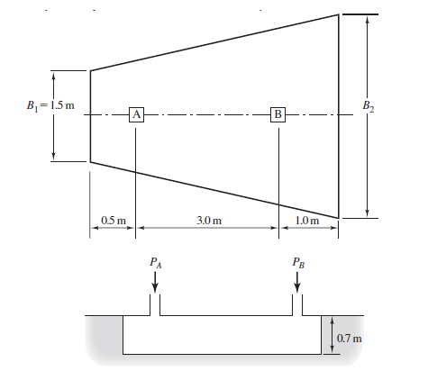
Figure 6.19
Proposed combined footing for Problems 6.9 and 6.10.

Learn your wayIncludes step-by-step video

Chapter 6 Solutions
Foundation Design: Pearson New International Edition
Additional Engineering Textbook Solutions
Structural Analysis (10th Edition)
Elementary Surveying (14th Edition)
Materials for Civil and Construction Engineers (4th Edition)
Elementary Surveying: An Introduction To Geomatics (15th Edition)
Starting Out with Programming Logic and Design (4th Edition)


- A 5.0 ft wide square footing is placed at 3.0 ft depth within the ground where c = 200 lb/ft2, = 25, and = 115.0 lb/ft3. Determine the ultimate bearing capacity of the footing using Terzaghis bearing capacity equation and the bearing capacity factors from Table 6.1. What is the maximum column load that can be allowed with a factor of safety of 3.0?arrow_forwardIf the soil exerts a trapezoidal distribution of load on the bottom of the footing, determine the intensities w1 and w2 of this distribution needed to support the column loadings.arrow_forwardA 460 mm reinforced concrete interior spiral column carries service loads of 1025 kN dead load and 715 kN live load (Figure 3). The column rest on a square spread footing 2.75 m x 2.75 m in dimension. The net ultimate soil pressure at the base of the footing is 314 kPa, f’c =21 MPa, fy = 345 MPa, clear cover is 75 mm and 25 mm-diameter bars, the allowable soil pressure is 250 kPa? Unit weight of soil is 17kN/m3 ; unit weight of concrete is 23.5 kN/m3. The underside of footing is 1.50m below the natural grade linearrow_forward
- Two footings of sizes 13 x 13 ft and 10 x 10 ft are placed 30 ft center to center apart at the same level and carry concentrated loads of 337 and 281 kips respectively. Compute the vertical pressure at depth 13 ft below point C midway between the centers of the footingarrow_forwardIf the footing 3.5m×3.5m, What is the critical factored shear force considering wide beam action? And If the footing is 3.5m×3.5m, What is the design shear strength of footing considering beam action?arrow_forwardConsider the strip footing shown in the figure below. The soil is a clay-dominant material with f’=26° and c’=3 kPa, Su = 70 kPa and γsat = 21 kN/m3. (Assume the footing to be very long). Calculate the ultimate bearing capacity of the foundation in kPa shortly after construction using the modified bearing capacity equationarrow_forward
- Determine the width needed for a wall footing to support loads: D = 263 KN/m and L = 176 KN/m. In addition, a moment of 53 KN m must be transferred from the column to the footing. Assume the footing is 450 mm. thick, its base is 1.5 m below the final grade, and qa = 192 KPa.arrow_forwardThe four columns shown below have the following loads and dimensions (in the directions shown): Columns 1 and 2: DL=150 kN; LL=150 kN; 40 cm x 30 cm Columns 3 and 4: DL=300 kN; LL=250 kN; 50 cm x 40 cm Estimate the design safety factor for bearing capacity failure if the footing is placed at a depth of 2 m below the surface of a sandly-silty soil with c = 25 kPa, φ = 15° and γ = 17 kN/m3. Given the allowable bearing capacity of the soil qa = 125 kPa. Calculate the minimum concrete thickness, d', of the footing based on punching shear under column 4 (only). Use fc’ = 24 MPa, fy = 345 MParrow_forwardRedo Problem 6.2 using the general bearing capacity equation [Eq. (6.28)]. A 5.0 ft wide square footing is placed at 3.0 ft depth within the ground where c = 200 lb/ft2, = 25, and = 115.0 lb/ft3. Determine the ultimate bearing capacity of the footing using Terzaghis bearing capacity equation and the bearing capacity factors from Table 6.1. What is the maximum column load that can be allowed with a factor of safety of 3.0?arrow_forward
- Refer to Problem 16.1. If a square footing with dimension 2 m 2 m is used instead of the wall footing, what would be the allowable bearing capacity? 16.1 A continuous footing is shown in Figure 16.17. Using Terzaghis bearing capacity factors, determine the gross allowable load per unit area (qall) that the footing can carry. Assume general shear failure. Given: = 19 kN/m3, c = 31kN/m2, =28, Df = 1.5 m, B = 2 m, and factor of safety = 3.5. Figure 16.17arrow_forwardRepeat Problem 20.2 based on LRFD using the following factors. Load factor for dead load = 1.25 Load factor for live load = 1.75 Strength reduction factor on the ultimate bearing capacity = 0.50 20.2 A continuous foundation is required in a soil where c = 10 kN/m2, =26 and = 19.0 kN/m3. The depth of the foundation will be 1.0 m. The dead load and the live load are 600 kN/m and 400 kN/m, respectively. Determine the required width for the foundation based on allowable stress design with FS = 3, using Eq. (16.3) and Table 16.1.arrow_forwardRedo Problem 16.1 with the following: = 115 lb/ft3, c = 1100 lb/ft2, =35, Df = 3.5 ft, B = 5 ft, and factor of safety = 4. 16.1 A continuous footing is shown in Figure 16.17. Using Terzaghis bearing capacity factors, determine the gross allowable load per unit area (qall) that the footing can carry. Assume general shear failure. Given: = 19 kN/m3, c = 31kN/m2, =28, Df = 1.5 m, B = 2 m, and factor of safety = 3.5. Figure 16.17arrow_forward
 Fundamentals of Geotechnical Engineering (MindTap...Civil EngineeringISBN:9781305635180Author:Braja M. Das, Nagaratnam SivakuganPublisher:Cengage Learning
 Principles of Foundation Engineering (MindTap Cou...Civil EngineeringISBN:9781337705028Author:Braja M. Das, Nagaratnam SivakuganPublisher:Cengage Learning
 Principles of Geotechnical Engineering (MindTap C...Civil EngineeringISBN:9781305970939Author:Braja M. Das, Khaled SobhanPublisher:Cengage Learning
 Principles of Foundation Engineering (MindTap Cou...Civil EngineeringISBN:9781305081550Author:Braja M. DasPublisher:Cengage Learning