Concept explainers
Videos
The composite beam shown is made by welding C200 × 17.1 rolled-steel channels to the flanges of a W250 × 80 wide-flange rolled-steel shape. Knowing that the beam is subjected to a vertical shear of 200 kN, determine (a) the horizontal shearing force per meter at each weld, (b) the shearing stress at point a of the flange of the wide-flange shape.
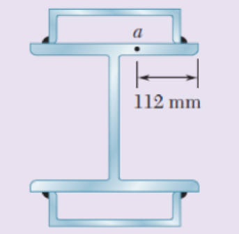
Fig. p6.97
(a)
The horizontal shearing force per meter at each weld.
Answer to Problem 97RP
The horizontal shearing force per meter at each weld is
Explanation of Solution
Given information:
The composite beam is made by welding
The beam is subjected to a vertical shear of
Calculation:
Provide the section properties of
The Area of the section is
The width of the flange is
The thickness of flange is
The moment of inertia of the section is
The centroid of the section is
Provide the section properties of
The overall depth of the section is
Thickness of flange is
Moment of inertia of the section is
Sketch the channel section above the neutral axis as shown in Figure 1.
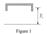
Refer to Figure 1.
Calculate the location of the centroid
Calculate the moment of inertia (I) for the composite beam as shown below.
Substitute
Calculate the first moment of area as shown below.
Calculate the first moment for the two welds (Q) as shown below.
Calculate the horizontal shear per unit length (q) as shown below.
Substitute
Calculate the shearing force per meter of weld for one weld as shown below.
Therefore, the horizontal shearing force per meter at each weld is
(b)
The shearing stress at point a of the flange.
Answer to Problem 97RP
The shearing stress at point a of the flange is
Explanation of Solution
Given information:
The beam is subjected to a vertical shear of
Calculation:
Refer to part (a).
The moment of inertia is
Sketch the channel section through point a as shown in Figure 2.
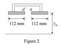
Refer to Figure 2.
The thickness of the section is
Substitute
Calculate the location of the centroid at point a
Calculate the first moment of area
Calculate the shear stress
Substitute
Therefore, the shearing stress at point a of the flange is
Want to see more full solutions like this?
Chapter 6 Solutions
Mechanics of Materials-Access (1 Sem. )


- Three 1 x 18-in. steel plates are bolted to four L6 x 6 x 1 angles to form a beam with the cross section shown. The bolts have a 78-in. diameter and are spaced longitudinally every 5 in. Knowing that the allowable average shearing stress in the bolts is 12 ksi, determine the largest permissible vertical shear in the beam. (Given: Ix= 6123 in4.)arrow_forwardA timber beam AB of length L and rectangular cross section carries a single concentrated load P at its midpoint C. (a) Show that the ratio Tm/ m of the maximum values of the shearing and normal stresses in the beam is equal to h/2L, where h and L are, respectively, the depth and the length of the beam. (b) Determine the depth h and the width b of the beam, knowing that L = 2 m, P = 40 kN, 7m = 960 kPa, and om = 12 MPa.arrow_forwardFor the wide-flange beam with the loading shown, determine the largest load P that can be applied, knowing that the maximum normal stress is 24 ksi and the largest shearing stress using the approximation τm= V/Aweb is 14.5 ksi.arrow_forward
- Three boards, each of 1.5 x3.5-in. rectangular cross section, are nailed together to form a beam that is subjected to a vertical shear of 250 lb. Knowing that the spacing between each pair of nails is 2.5 in., determine the shearing force in each nail.arrow_forwardLink AB, of width b = 50 mm and thickness t = 6 mm, is used to support the end of a horizontal beam. Knowing that the average normal stress in the link is –140 MPa, and that the average shearing stress in each of the two pins is 80 MPa, determine (a) the diameter d of the pins, (b) the average bearing stress in the link.arrow_forwardAn elastomeric bearing (G=130 psi) is used to support a bridge girder as shown to provide flexibility during earthquakes. The beam must not displace more than 38 in. when a 5-kip lateral load is applied as shown. Knowing that the maximum allowable shearing stress is 60 psi, determine (a) the smallest allowable dimension b, (b) the smallest required thickness a.arrow_forward
- A composite beam is made by attaching the timber and steel portions shown with bolts of 12-mm diameter spaced longitudinally every 200 mm. The modulus of elasticity is 10 GPa for the wood and 200 GPa for the steel. For a vertical shear of 4 kN, determine (a) the average shearing stress in the bolts, (b) the shearing stress at the center of the cross section.arrow_forwardTwo wooden planks, each 7/8 in thick and 6in wide, are joined by the glued mortise joint shown. Knowing that the wood used shears off along its grain when the average shearing stress reaches 120psi, determine the smallest allowable length d of the cuts if the joint is to withstand an axial load of magnitude P=1200-lb. Note: Seven surfaces carry the load, P=1200-lbarrow_forwardA square box beam is made of two 20 x 80-mm planks and two 20 x 120-mm planks nailed together as shown. Knowing that the spacing between the nails is s= 30 mm and that the vertical shear in the beam is V=1200 N, determine (a) the shearing force in each nail, (b) the maximum shearing stress in the beam.arrow_forward
- A) The four cross sections shown have different characteristics when subjected to a vertical shear force. Which of the four geometries shown has the largest value for the moment of the area, Q, about the neutral axis? B) Which of the four geometries shown has the smallest value for its moment of inertia about the x axis? C) Given that all four geometries are subjected to the same vertical shear force V, which of the four has the smallest value for the maximum shear stress?arrow_forwardKnowing that a given vertical shear V causes a maximum shearing stress of 50 MPa in a thin-walled member having the cross section shown, determine the corresponding shearing stress at (a) point a, (b) point b, (c) point c.arrow_forwardDetermine the maximum load F that can be applied at the free end of a 3 m cantilever beam of universal rolled-steel beam cross-section, 356 mm deep, with a moment of inertia of 142 × 106 mm4, if the allowable stress is 76 MPa.arrow_forward
 Elements Of ElectromagneticsMechanical EngineeringISBN:9780190698614Author:Sadiku, Matthew N. O.Publisher:Oxford University Press
 Mechanics of Materials (10th Edition)Mechanical EngineeringISBN:9780134319650Author:Russell C. HibbelerPublisher:PEARSON
 Thermodynamics: An Engineering ApproachMechanical EngineeringISBN:9781259822674Author:Yunus A. Cengel Dr., Michael A. BolesPublisher:McGraw-Hill Education
 Control Systems EngineeringMechanical EngineeringISBN:9781118170519Author:Norman S. NisePublisher:WILEY
 Mechanics of Materials (MindTap Course List)Mechanical EngineeringISBN:9781337093347Author:Barry J. Goodno, James M. GerePublisher:Cengage Learning
 Engineering Mechanics: StaticsMechanical EngineeringISBN:9781118807330Author:James L. Meriam, L. G. Kraige, J. N. BoltonPublisher:WILEY