
Concept explainers
Videos
A Pratt roof truss is loaded as shown. Determine the force members FH, FI, and GI.
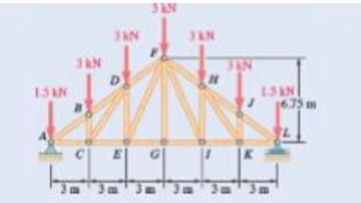
Fig. P6.55 and P6.56
The force in the members
Answer to Problem 6.56P
The force in the members
Explanation of Solution
The Pratt roof truss is loaded as shown in the figure. There is load at all the point on the top. The free body diagram of the given arrangement is given by Figure 1.
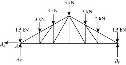
Figure 1
The total load on the truss is given from the figure as,
By symmetry the
The section’s free body diagram is given as,
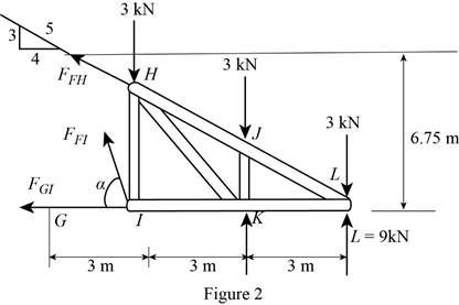
The tangent of the angle
The angle is derived from the tangent value as,
From the diagram the sum of the moments in the counter clockwise direction about
From the diagram the sum of the moments in the counter clockwise direction about
From the diagram the sum of the moments in the counter clockwise direction about
Conclusion:
Solve for
Solve for
Solve for
Therefore, the force in the members
Want to see more full solutions like this?
Chapter 6 Solutions
Vector Mechanics for Engineers: Statics and Dynamics


- The T-shaped bracket shown is supported by a small wheel at E and pegs at C and D . Neglecting the effect of friction, determine the reactions at C, D, and E when 0= 30°.arrow_forwardThe cab and motor units of the front-end loader shown are connected by a vertical pin located 2 m behind the cab wheels. The distance from C to D is 1 m. The center of gravity of the 300-kN motor unit is located at Gm , while the centers of gravity of the 100-kN cab and 75-kN load are located, respectively, at Gc and GI. . Knowing that the machine is at rest with its brakes released, determine (a) the reactions at each of the four wheels, (b) the forces exerted on the motor unit at C and D.arrow_forwardThe cab and motor units of the front-end loader shown are connected by a vertical pin located 2 m behind the cab wheels. The distance from C to D is 1 m. The center of gravity of the 300-kN motor unit is located at Gm, while the centers of gravity of the 100-kN cab and 75-kN load are located, respectively, at Gc and Gl. Knowing that the front-end loader is at rest with its brakes released, determine(a) the reactions at each of the four wheels, (b) the forces exertedon the motor unit at C and D.arrow_forward
- Members ABC and CDE are pin-connected at C and supported by four links. For the loading shown, determine the force in each link.arrow_forwardA 48-in. boom is held by a ball-and-socket joint at C and by two cables BF and DAE; cable DAE passes around a frictionless pulley at A. For the loading shown, determine the tension in each cable and the reaction at C.arrow_forwardFor the steel truss and loading shown, determine the magnitude of the force (lb) of member BD, knowing that x = 13.5 ft, y = 7.5 ft, and P = 27,680 lb.arrow_forward
- The assembly shown consists of an 80-mm rod AF that is welded to a cross frame consisting of four 200-mm arms. The assembly is supported by a ball-and-socket joint at F and by three short links, each of which forms an angle of 45° with the vertical. For the loading shown, determine (a) the tension in each link, (b) the reaction at F.arrow_forwardTwo members, each consisting of a straight and a quarter-circular portion of rod, are connected as shown and support a 75-lb load at A . Determine the internal forces at point J.arrow_forwardThe T-shaped bracket shown is supported by a small wheel at E and pegs at C and D . Neglecting the effect of friction, determine (a) the smallest value of 0 for which the equilibrium of the bracket is maintained, (b) the corresponding reactions at C, D, and E.arrow_forward
- Arm ABC is connected by pins to a collar at B and to crank CD at C Neglecting the effect of friction, determine the couple M required to hold the system in equilibrium 'when 0= 90°.Fig.P6.134arrow_forwardTwo 9-in.-diameter pipes (pipe 1 and pipe 2) are supported every 7.5 ft by a small frame like that shown. Knowing that the combined weight of each pipe and its contents is 30 lb/ft and assuming frictionless surfaces, determine the components of the reactions at A and G.arrow_forwardMember ABC is supported by a pin and bracket at B and by an inextensible cord attached at A and C and passing over a frictionless pulley at D. The tension may be assumed to be the same in portions AD and CD of the cord. For the loading shown and neglecting the size of the pulley, determine the tension in the cord and the reaction at B.arrow_forward
 Elements Of ElectromagneticsMechanical EngineeringISBN:9780190698614Author:Sadiku, Matthew N. O.Publisher:Oxford University Press
 Mechanics of Materials (10th Edition)Mechanical EngineeringISBN:9780134319650Author:Russell C. HibbelerPublisher:PEARSON
 Thermodynamics: An Engineering ApproachMechanical EngineeringISBN:9781259822674Author:Yunus A. Cengel Dr., Michael A. BolesPublisher:McGraw-Hill Education
 Control Systems EngineeringMechanical EngineeringISBN:9781118170519Author:Norman S. NisePublisher:WILEY
 Mechanics of Materials (MindTap Course List)Mechanical EngineeringISBN:9781337093347Author:Barry J. Goodno, James M. GerePublisher:Cengage Learning
 Engineering Mechanics: StaticsMechanical EngineeringISBN:9781118807330Author:James L. Meriam, L. G. Kraige, J. N. BoltonPublisher:WILEY