
Concept explainers
Videos
6.70 through 6.74 classify as determinate or indeterminate. (All members act both in tension and in compression.)
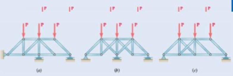
Fig. P6.74
(a)
Classify the given structure as completely, partially, or improperly constrained and if completely constrained, further classify as determinate or indeterminate.
Answer to Problem 6.74P
The given structure is completely constrained and determinate.
Explanation of Solution
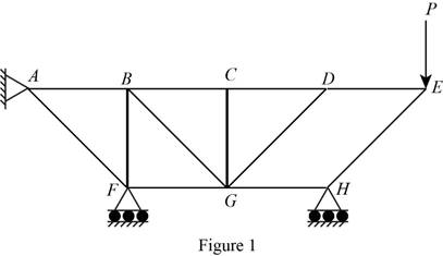
The structure is shown in Fig. P6.74 (a). The arrangement can be redrawn by labeling different points in the truss and is given in Figure 1.
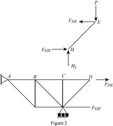
The free-body diagram of the section
Write the condition for a truss to be completely constrained.
Here,
Write the condition for a truss to be partially constrained.
Write the expression for a truss to be indeterminate.
Write the expression for the condition for equilibrium.
Here,
Conclusion:
For the given truss,
Compute
Compute
So, for the given system,
Apply the condition for equilibrium in equation (IV) about point
Apply the condition for equilibrium in equation (V) about various points of the structure in the free-body diagrams given in Figure 2.
So, the truss
Therefore, the given structure is completely constrained and determinate.
(b)
Classify the given structure as completely, partially, or improperly constrained and if completely constrained, further classify as determinate or indeterminate.
Answer to Problem 6.74P
The given structure is partially constrained.
Explanation of Solution
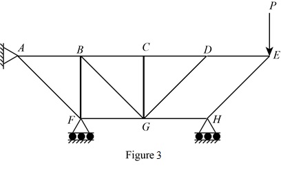
The structure is shown in Fig. P6.74 (b). The arrangement can be redrawn by labeling different points in the truss and is given in Figure 3.
From equations (I), (II), and (III), the conditions for the state of constrain of the structure is as follows,
Conclusion:
For the given truss,
Compute
Compute
So, for the given system,
Therefore, the given structure is partially constrained.
(c)
Classify the given structure as completely, partially, or improperly constrained and if completely constrained, further classify as determinate or indeterminate.
Answer to Problem 6.74P
The given structure is completely constrained and indeterminate.
Explanation of Solution
The structure is shown in Fig. P6.74 (c). The arrangement can be redrawn by labeling different points in the truss and is given in Figure 4.

From equations (I), (II), and (III), the conditions for the state of constrain of the structure is as follows,
Conclusion:
For the given truss,
Compute
Compute
So, for the given system,
Therefore, the given structure is completely constrained and indeterminate.
Want to see more full solutions like this?
Chapter 6 Solutions
Connect 1 Semester Access Card for Vector Mechanics for Engineers: Statics and Dynamics
Additional Engineering Textbook Solutions
Thermodynamics: An Engineering Approach
Fluid Mechanics Fundamentals And Applications
Heating Ventilating and Air Conditioning: Analysis and Design
DESIGN OF MACHINERY
Degarmo's Materials And Processes In Manufacturing
EBK FUNDAMENTALS OF THERMODYNAMICS, ENH


- Fig. P6.45 and P6.46 36 kips 36 kips Answer For = 60.0 kips C; FDG = 15.00 kips C. E G 4 panels at 10 ft = 40 ft 6.46 Determine the force in members DF and DG of the truss shown. 7.5 ftarrow_forward6.1 through 6.8 Using the method of joints, determine the force in each member of the truss shown. State whether ch member is in tension or compression. 375 lb A 8 ft 500 lb В C O D 8.4 ft Fig. P6.4arrow_forwardProblem 4.9 The length of the bar 30 AP is 650 mm. The radius of the 45° pulley is 120 mm. Equal forces T = 50 N are applied to the ends of the cable. What is the sum of the moments of the forces (a) about A; (b) about P. %3D Solution: 45°arrow_forward
- -2 m -2 m – 4.5 kN 1.4 kN E 2.8 kN Do G 0.5 m F 1 kN I kN B 3 m I kN. I kN A |C I 1 m '1m 1 m 1 m Fig. P6.15 and P6.16 6.16 For the Gambrel roof truss shown, determine the force in members CG and CI and in each of the members located to the right of the centerline of the truss. State whether each member is in tension or compression.arrow_forward6.9 Determine the force in each member of the truss shown. State 298 Analysis of Structures whether each member is in tension or compression. 10 kips B C D 2 kips 7.5 ft |H 2 kips 2 kips 3.6 ft G D 1 kip 1 kip B - 6 ft 6 ft 6 ft 6 ft- 9 ft Fig. P6.9 Н.arrow_forward(3) Using the method of sections, determine the force in member CG and state whether it is in tension or compression. 1.5 m, 1.5 m, 1.5 m. 1.5 m, 1.5 m, 1.5 m 2 kN 2 kN 12 kN 2 kN 1 kN 2 kN 1 kN F. H. 2 m Fig. P6.10arrow_forward
- Problem 1 (a) (b) compression. Answers: (a) RAx= Rcx = . For the given truss structure below: Determine the reactions and their directions. Determine the forces, FBC, FBE, and FEF. Specify whether the member is in tension or (b) FBC = 45° You ( - 4 m (direction: (direction: ) FBE = B + ) ) 12kN 4 m Ray = Rcy= E 12 kN () 4 m FEF= 8 kN D 3 m (direction: ) (direction: ) ()arrow_forwardProblem 1.6 Truss loaded as shown, 12 ft 8 ft A 8 ft 36 kips 8 ft 8 ft Working Stress: 20 ksi in tension 12 ksi in compression Required: Smallest allowable cross sectional area of member BD, BE and CE.arrow_forward6.42 A floor truss is loaded as shown. Determine the force in 250 lb 500 lb 500 lb 375 lb 250 |b 250 |b 125 ||. 4 ft 4 ft bers CF, EF, and EG. 4 ft 4 ft 4 ft 4 ft E GV B. 2 ft Fig. P6.42 and P6.43arrow_forward
- 6.43 Determine the force in members BD and DE of the truss shown. Answer 6.44 Determine the force in members DG and EG of the truss shown. Answer Fig. P6.43 and P6.44 2.4 m 2.4 m 2.4 m 135 KN 135 kN 135 kN A B D F 4.5 m с E Garrow_forward(4) A barrel weighing 200 lb is lifted using the tongs as shown. Knowing that a = 4 in, what is the force at B on 6 in. 9 in. member BC? А В D 18 in. Fig. P6.135arrow_forwardFig. Q3 7. Determine the force in each member of t truss in Fig. Q4 and state if the membere are in tension or compression. 3 kN 2 kN -3 m- -3 m- B C FBA 3kN (T), FRA = [FcD = 3.61kN (C), FCB %3D 4 m 3kN (T), FRD = 3kN (C), FDA %3D Draw FRE = 6.31KN (C)] FE %3D E Fig. Q4 521Carrow_forward
 Elements Of ElectromagneticsMechanical EngineeringISBN:9780190698614Author:Sadiku, Matthew N. O.Publisher:Oxford University Press
 Mechanics of Materials (10th Edition)Mechanical EngineeringISBN:9780134319650Author:Russell C. HibbelerPublisher:PEARSON
 Thermodynamics: An Engineering ApproachMechanical EngineeringISBN:9781259822674Author:Yunus A. Cengel Dr., Michael A. BolesPublisher:McGraw-Hill Education
 Control Systems EngineeringMechanical EngineeringISBN:9781118170519Author:Norman S. NisePublisher:WILEY
 Mechanics of Materials (MindTap Course List)Mechanical EngineeringISBN:9781337093347Author:Barry J. Goodno, James M. GerePublisher:Cengage Learning
 Engineering Mechanics: StaticsMechanical EngineeringISBN:9781118807330Author:James L. Meriam, L. G. Kraige, J. N. BoltonPublisher:WILEY