
Videos
The force exerted by each cylinder shown in figure
Answer to Problem 6.158P
The force exerted by the cylinder
Explanation of Solution
Take all
Let P is the force exerted on the bucket at J.
The magnitude of force
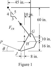
The free body diagram of the bucket is sketched below as figure 1.
Here,
Write the expression for the moment at
Here,
Above equation implies that net moment at any point is the sum of product of each force acting on the system and perpendicular distance of the force and the point.
The moment at
Thus, the complete expression of net anticlockwise moment
Here,
At equilibrium, the sum of the moment acting at
Write the expression for the total moment acting at
From figure 1 , write the expression for the
From figure 1 , write the expression for the
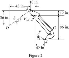
The free body diagram of the bucket and arm
Here,
Write the expression for the moment at
Here,
Above equation implies that net moment at any point is the sum of product of each force acting on the system and perpendicular distance of the force and the point.
The moment at
Thus, the complete expression of net anticlockwise moment
Here,
At equilibrium, the sum of the moment acting at
Write the expression for the total moment acting at
From figure 2 , write the expression for the
Geometry of cylinder
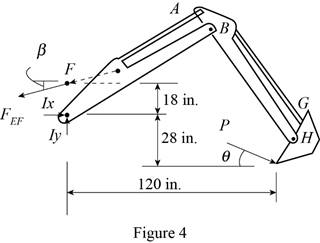
The free body diagram of the bucket and both arms is sketched below as figure 4.
Here,
Write the expression for the moment at
Here,
Above equation implies that net moment at any point is the sum of product of each force acting on the system and perpendicular distance of the force and the point.
The moment at
Thus, the complete expression of net anticlockwise moment
Here,
At equilibrium, the sum of the moment acting at
Write the expression for the total moment acting at
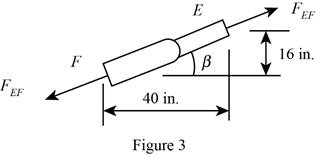
From figure 3 , write the expression for the
Calculation:
Substitute
The negative sign indicate that the cylinder undergoes compression.
Substitute
The negative sign indicate that the cylinder undergoes compression.
Rearrange the equation (X) to get

Substitute
The positive sign indicate that the cylinder
Therefore, the force exerted by the cylinder
Want to see more full solutions like this?
Chapter 6 Solutions
Connect 1 Semester Access Card for Vector Mechanics for Engineers: Statics and Dynamics


- Find the magnitudes of the pin reactions at A, C and E caused by the 1800-N.m couple.arrow_forward4.81 When activated by the force P, the gripper on a robotic arm is able to pick up objects by applying the gripping force F. Given that P = 120 N, calculate the gripping force for the position shown. 160 mm - 250 mm 52 mm- B m m. D m m. Fig. P4.81arrow_forwardSolve Prob. 2.4 by trigonometry.(Reference to Problem 2.4):Two structural members B and C are bolted to bracket A . Knowing that both members are in tension and that P = 6 kips and Q = 4 kips, determine graphically the magnitude and direction of the resultant force exerted on the bracket using (a) the parallelogram law, (b) the triangle rule.arrow_forward
- 4.26 Construct the shear force and bending moment diagrams for the beamshown by the area method. Neglect the weight of the beamarrow_forward360 mm 920 mm lo 600 mm 900 mm C.arrow_forwardThe 25-m crane boom AO lies in the yz plane. Determine the maximum permissible tension in cable AB if the absolute value of moments about the coordinate axes of the force exerted on A by cable AB must be as follows: |Mx| ≤ 60 kN.m. |My| ≤ 12 kN.m. |Mz| ≤ 8 kN.m.arrow_forward
- Problem 4.41 The hydraulic cylinder BC exerts a 2200-lb force on the boom of the crane at C. The force is parallel to the cylinder. The angle a = 40°. What is the moment of the force about A? 49- Ans. M=13040 ft.ibarrow_forwardThe force P has a magnitude of 300 N and is applied at the end C of the rod ABC, as shown. Assuming a=35° and B=50°, replace P with C B P (a) an equivalent force-couple system at 300 mm В, (b) an equivalent system formed by two parallel forces applied at A and B. A 200 mmarrow_forwardQ.4 Determine the magnitude of the moment of the force Fc about the hinge axis aa of the door. d 60 mm B 35 kN 170 mmarrow_forward
- The tailgate of a car is supported by the hydraulic lift BC If the lift exerts a 125-lb force directed along its centerline on the ball and socket at B, determine the moment of the force about A.arrow_forwardNeeds Complete solution with 100 % accuracy.arrow_forwardEXERCISE 5.31 The right triangular plate is welded to the shaft, which rotates at constant speed. Determine the force-couple acting at bearing A that is equivalent to the force system the bearings must exert to sustain this motion. a 61 aarrow_forward
 Elements Of ElectromagneticsMechanical EngineeringISBN:9780190698614Author:Sadiku, Matthew N. O.Publisher:Oxford University Press
 Mechanics of Materials (10th Edition)Mechanical EngineeringISBN:9780134319650Author:Russell C. HibbelerPublisher:PEARSON
 Thermodynamics: An Engineering ApproachMechanical EngineeringISBN:9781259822674Author:Yunus A. Cengel Dr., Michael A. BolesPublisher:McGraw-Hill Education
 Control Systems EngineeringMechanical EngineeringISBN:9781118170519Author:Norman S. NisePublisher:WILEY
 Mechanics of Materials (MindTap Course List)Mechanical EngineeringISBN:9781337093347Author:Barry J. Goodno, James M. GerePublisher:Cengage Learning
 Engineering Mechanics: StaticsMechanical EngineeringISBN:9781118807330Author:James L. Meriam, L. G. Kraige, J. N. BoltonPublisher:WILEY